Waste heat recovery system for environment-friendly coating mechanical equipment

A technology of waste heat recovery system and mechanical equipment, applied in heat exchange equipment, lighting and heating equipment, devices for coating liquid on surfaces, etc., can solve problems such as thermal energy waste, atmospheric environmental pollution, etc. The effect of recycling and simple structure

Inactive Publication Date: 2020-10-09
王小珍
View PDF8 Cites 5 Cited by
  • Summary
  • Abstract
  • Description
  • Claims
  • Application Information

AI Technical Summary

Problems solved by technology

[0004] The purpose of the present invention is to solve the disadvantages in the prior art that the exhaust gas in the drying chamber is discharged into the atmosphere at a relatively high temperature, causin

Method used


Image

  • Waste heat recovery system for environment-friendly coating mechanical equipment
  • Waste heat recovery system for environment-friendly coating mechanical equipment
  • Waste heat recovery system for environment-friendly coating mechanical equipment

Examples


Example Embodiment

[0030] Embodiment one

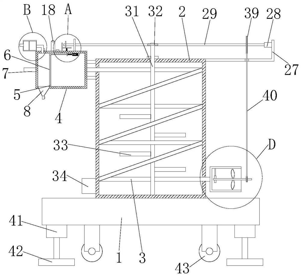
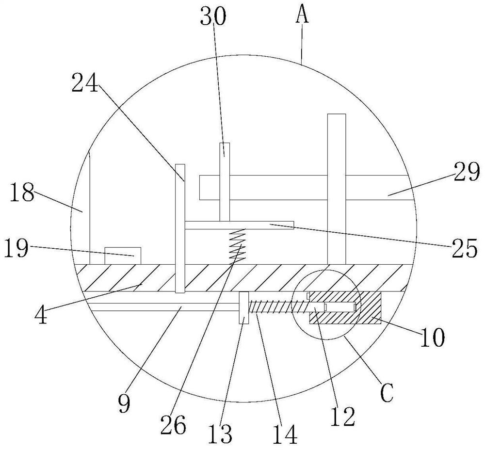
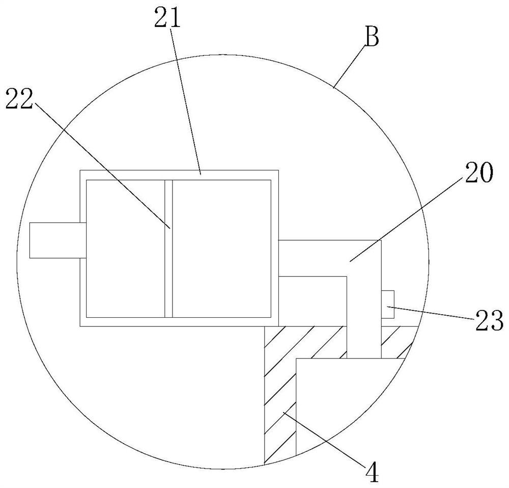
[0031] refer to Figure 1-5 , a waste heat recovery system for coating environmental protection machinery and equipment, including a conveying plate 1, a box 2 is fixedly installed on the top of the conveying plate 1, a spiral coil 3 is arranged on the inner wall of the box 2, and one end of the spiral coil 3 is fixedly installed There is a processing box 4, a sliding frame 5 is slidably installed in the processing box 4, a filter screen 6 is fixedly installed in the sliding frame 5, and a collecting bucket 8 is fixedly connected to the bottom of the processing box 4, and a valve is arranged in the collecting bucket 8, and the processing box 4 One side of the sliding frame 5 is fixedly equipped with an intake pipe 7, one side of the sliding frame 5 is fixedly installed with a side of the contact plate 9, and a fixed seat 10 is fixedly installed on the top inner wall of the processing box 4, and one side of the fixed seat 10 is provided with a chute 11....

Example Embodiment

[0041] Embodiment two

[0042] refer to Figure 1-5 , a waste heat recovery system for coating environmental protection machinery and equipment, including a conveying plate 1, a box body 2 is fixed on the top of the conveying plate 1 through bolts, a spiral coil 3 is arranged on the inner wall of the box body 2, and one end of the spiral coil 3 The processing box 4 is fixedly installed by bolts, the sliding frame 5 is slidably installed in the processing box 4, the filter screen 6 is fixedly installed by bolts in the sliding frame 5, and the bottom of the processing box 4 is fixedly communicated with a collecting bucket 8, and the collecting bucket 8 is equipped with There is a valve, one side of the treatment box 4 is fixed with an air inlet pipe 7 by bolts, one side of the sliding frame 5 is fixed with a side of the contact plate 9 by bolts, and the top inner wall of the treatment box 4 is fixed with a fixed seat by bolts 10. One side of the fixed seat 10 is provided with a...


PUM


Abstract

The invention belongs to the technical field of waste heat recovery of environment-friendly machinery, and particularly relates to a waste heat recovery system for environment-friendly coating mechanical equipment. The waste heat recovery system aims at solving the problems that waste gas in an existing drying chamber is discharged into the atmosphere at a high temperature, so that atmospheric environment pollution is caused, and a large amount of heat energy is wasted. According to the technical scheme, the waste heat recovery system comprises a conveying plate. A box body is mounted at the top of the conveying plate, a spiral coil is arranged on the inner wall of the box body, and a treatment box is fixedly mounted at one end of the spiral coil. A sliding frame is slidably mounted in thetreatment box, a filter screen is fixedly mounted in the sliding frame, and a collecting hopper fixedly communicates with the bottom of the treatment box. A valve is arranged in the collecting hopper, and an air inlet pipe is fixedly mounted on one side of the treatment box. One side of a contact plate is fixedly mounted on one side of the sliding frame, and a fixed seat is fixedly mounted on theinner wall of the top of the treatment box. By the waste heat recovery system, waste heat can be recycled, waste gas can be treated, an alarm can be given and pressure can be relieved when the filterscreen is blocked, the structure is simple, and use is convenient.

Description

technical field [0001] The invention belongs to the technical field of waste heat recovery of environmental protection machinery, and in particular relates to a waste heat recovery system of coating environmental protection machinery and equipment. Background technique [0002] Coating refers to the covering of metal and non-metal surfaces with a protective or decorative layer, and coating machinery is a rapidly developing industry based on coating. After the coating is completed, it needs to be dried. [0003] In the prior art, the exhaust gas in the drying room is discharged into the atmosphere at a relatively high temperature, causing atmospheric environmental pollution and a large waste of heat energy. Therefore, we propose a waste heat recovery system for coating environmental protection machinery and equipment , to solve the above problems. Contents of the invention [0004] The purpose of the present invention is to solve the disadvantages in the prior art that the...

Claims


Application Information

Patent Timeline
IPC IPC(8): F28D7/02F28F19/01F28F27/00F28F13/12F28F9/007B05D3/04B01D46/12B01D46/00
CPCF28D7/024F28F19/01F28F27/00F28F13/125F28F9/007B05D3/0413B01D46/12B01D46/56B01D46/76Y02P70/10
Inventor 王小珍
Owner 王小珍
Why Eureka
Try Eureka