
Proton membrane fixing device used for dual-face coating

A technology of fixing device and coating device, which is applied in the direction of surface coating liquid device, coating, pretreatment surface, etc., and can solve problems such as high environmental requirements, membrane electrode hole defects, and depressions

Inactive Publication Date: 2020-10-20
DONGFENG MOTOR CORP HUBEI
View PDF13 Cites 0 Cited by
  • Summary
  • Abstract
  • Description
  • Claims
  • Application Information

AI Technical Summary

Problems solved by technology

The patent only studies the catalyst formula, but the coating device does not mention
[0006] The patent "A Fuel Cell Membrane Electrode Preparation Slurry Supply System" (Patent No. 201820988025.0) of the Kunshan Innovation Research Institute of Nanjing University discloses a fuel cell membrane electrode slurry supply system, which includes a frame, a storage system, Syringe pump, three-way solenoid valve, etc., this device can realize the continuous feeding of catalyst slurry, but its common pipeline leads to the mutual contamination of two different types of catalyst slurry when the cathode and anode catalysts are sprayed on both sides
[0007] The patent "Fuel Cell Membrane Electrode Preparation Jig and Its Processing Technology" (Patent No. CN 103811770 A) of the Kunshan Innovation Research Institute of Nanjing University discloses a jig for fixing the proton exchange membrane. The jig consists of a metal upper frame, a metal lower frame, Long tail clip, suction chassis, film-laying chassis, spraying mask, hot-pressed pad, hot-pressed assembly backing plate, two hot-pressed positioning plates, hot-pressed upper cover, hot-pressed lower cover, hot-pressed thickness limiter block, which avoids the repeated disassembly and assembly of the proton exchange membrane caused by the replacement of the fixture in each process of membrane electrode preparation, thereby avoiding the wrinkles, position shift, pollution and even damage of the proton exchange membrane in the membrane electrode, and improving the membrane electrode product. Yield rate saves fixture assembly time, but this device is not suitable for fixing proton exchange membranes during continuous production, and the edges are easily damaged
[0008] The patent "an electrostatic spraying device for preparing fuel cell membrane electrodes" (Patent No. CN 106861958A) of the Dalian Institute of Chemical Physics, Chinese Academy of Sciences discloses an electrostatic spraying device suitable for the preparation of fuel cell membrane electrodes. The device includes a housing, Vacuum heating table, slurry supply system with stirring, electrostatic spray head, and electrostatic generator. Although this device can improve the spraying efficiency of the catalyst and the uniformity of the catalytic layer through electrostatic repulsion, the spraying efficiency of the device is low. It has high environmental requirements and cannot realize fully automatic double-sided spraying. At the same time, the way of vacuum adsorption device to fix the proton exchange membrane is easy to cause hole defects in the membrane electrode, which cannot meet the quality requirements of the membrane electrode prepared in batches.
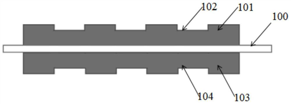
like figure 1 As shown, the proton membrane 100 is directly adsorbed on the stainless steel plate with openings. This large-diameter hole can indeed ensure firm adsorption, but it will also cause depressions here, which will adversely affect the slurry coating and affect the three-in-one process. The flatness and uniformity of a film, such as the anode depression 102 produced on the anode catalyst layer 101, and the cathode depression 104 produced on the cathode catalyst layer 103

Method used


Image

  • Proton membrane fixing device used for dual-face coating
  • Proton membrane fixing device used for dual-face coating
  • Proton membrane fixing device used for dual-face coating

Examples


Embodiment Construction

[0036] The following specific examples illustrate the present invention in further detail.

[0037] Such as figure 1 Shown is a schematic diagram of defects in the catalyst layer on the proton membrane in the prior art, which has been described in the background technology and will not be repeated.

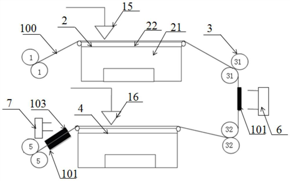
[0038] Such as figure 2As shown, a proton membrane fixing device for double-sided coating provided by the present invention includes a first traction roller group 1, an anode fixing device 2, an overturning device 3, and a cathode fixing device arranged in sequence along the advancing direction of the proton membrane 4. The second pulling roller set 5 , and the anode coating head 15 arranged above the anode fixing device 2 , and the cathode coating head 16 arranged above the cathode fixing device 4 . The anode fixing device 2 and the cathode fixing device 4 are correspondingly arranged on the same horizontal side of the turning device 3 up and down ( figure 2 middle left side...


PUM

PropertyMeasurementUnit
pore sizeaaaaaaaaaa
pore sizeaaaaaaaaaa
pore sizeaaaaaaaaaa

Abstract

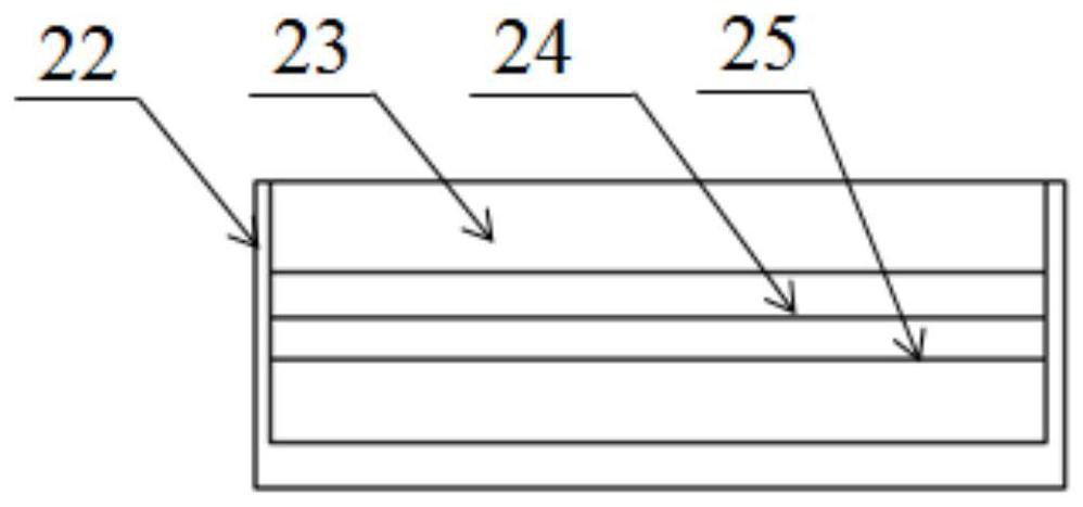
The invention discloses a proton membrane fixing device used for dual-face coating. The device is characterized by comprising a first traction roller set, an anode fixing device, a turnover device, acathode fixing device and a second traction roller set which are sequentially mounted in the advancing direction of a proton membrane, the anode fixing device and the cathode fixing device are locatedon the horizontal same side of the turnover device, the turnover device comprises an upper turnover roller set and a lower turnover roller set which are oppositely mounted up and down, an anode drying detection device is mounted between the upper turnover roller set and the lower turnover roller set, a cathode drying detection device is mounted between the cathode fixing device and the second traction roller set, a porous composite panel is mounted on the top of the anode fixing device, vacuum absorbing fixing of a proton exchange film can be achieved, compared with the manner that in the prior art, a stainless steel plate is directly opened, a micro-hole layer on the top of the porous composite panel flattens and absorbs the film during vacuum pumping, and the thickness of a coated catalyst is uniform.

Description

technical field [0001] The invention relates to the field of fuel cells, in particular to a proton membrane fixing device for double-sided coating. Background technique [0002] A proton exchange membrane fuel cell is a power generation device that uses hydrogen as fuel to directly convert chemical energy into electrical energy. Fuel cells have the advantages of high energy density, fast start-up speed, low operating temperature, and non-polluting products, which make them have potential application value in the field of automotive power. The structure of the membrane electrode, usually an anode catalyst layer, a proton exchange membrane, and a cathode catalyst layer, is called a three-in-one membrane electrode assembly. As the place where the electrochemical reaction of the fuel cell occurs, the performance of the membrane electrode directly determines the performance and reliability of the fuel cell. Although research institutions have made significant progress in the pr...

Claims


Application Information

Patent Timeline
Patent Type & Authority Applications(China)
IPC IPC(8): B05C9/04B05C9/14B05C13/02B05C5/02B05C11/10B05D3/02H01M8/1004H01M4/88
CPCB05C5/0245B05C9/04B05C9/14B05C11/1005B05C13/02B05D3/0263H01M4/881H01M4/8828H01M8/1004Y02E60/50
Inventor 史建鹏覃博文张新丰李洪涛张泽
Owner DONGFENG MOTOR CORP HUBEI
Learn More