a smart sensor

A technology of smart sensors and photosensitive devices, applied in the field of sensors, can solve the problems of laborious debugging, detection failure, and troublesome design.

Active Publication Date: 2021-04-23
CHANGCHUN INST OF TECH
View PDF10 Cites 0 Cited by
  • Summary
  • Abstract
  • Description
  • Claims
  • Application Information

AI Technical Summary

Problems solved by technology

[0004] The prior art has the following disadvantages: 1. The cost of the safety protection device in the prior art is high. The safety protection device is composed of a photoelectric transmitter and a photoelectric receiver and a signal cable and a control cable connected between them. When a light curtain needs to be formed, Multiple pairs of photoelectric transmitters and photoelectric receivers must be used to form a light curtain with gaps. Engineers design to form a light curtain and need to design the cooperation of multiple pairs of photoelectric transmitters and photoelectric receivers.
[0005] 2. The signal transmission cable is easily disturbed by the strong electromagnetic environment, which causes sequence errors when the device scans, and the cable length is limited and the protection distance is short
[0006] 3. In the prior art, there is a gap between two adjacent photoelectric emitting elements of the safety protection device. If the blocking object is small enough and located in the gap area between the two grating bars, the existence of the blocking object cannot be detected, and there is room for improvement.
[0007] 4. The safety protection device in the existing technology cannot self-check in real time. If it suddenly fails during the use of the equipment, the problem cannot be found in real time, which may lead to detection failure or personal safety accidents. There is room for improvement
[0008] 5. There are gaps that cannot be detected in the existing technology. The hand may bypass the infrared rays and enter the dangerous area, which affects safety and has room for improvement.

Method used


Image

  • a smart sensor
  • a smart sensor
  • a smart sensor

Examples


Embodiment Construction

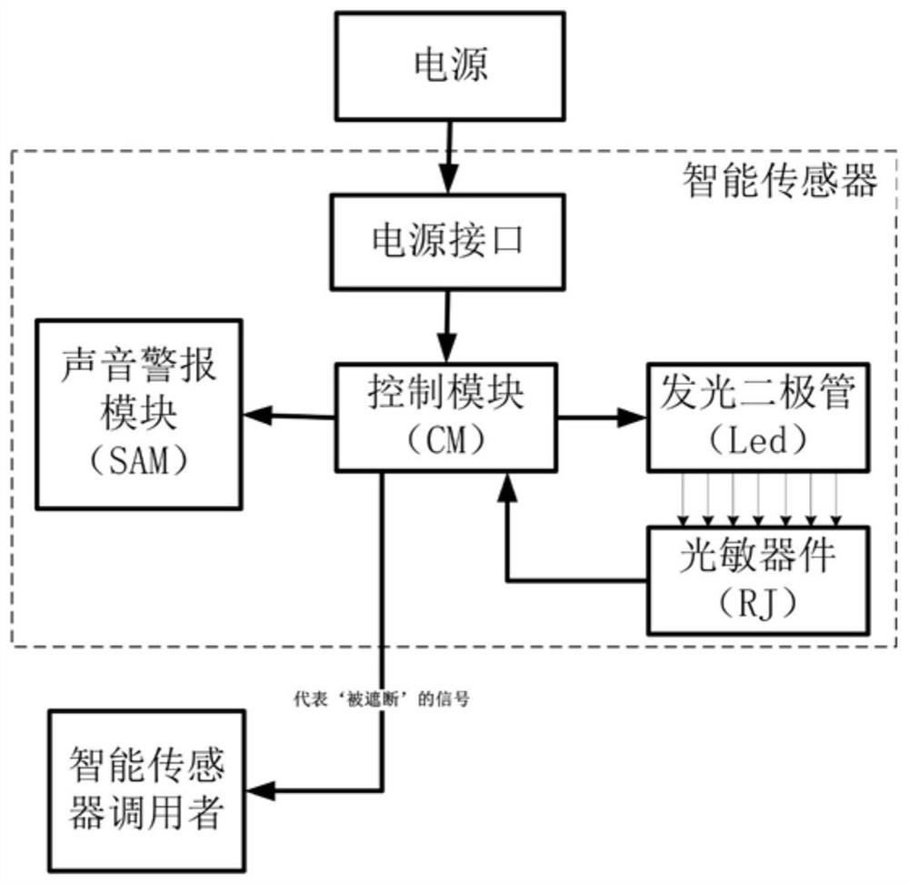
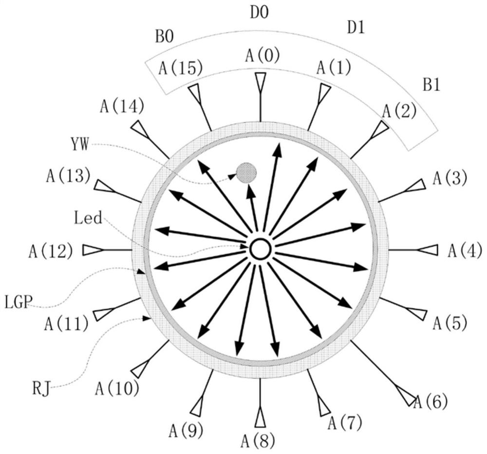
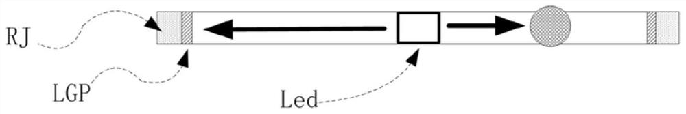
[0066] Such as Figure 1-8 As shown, an intelligent sensor includes a first capacitor, a second capacitor, a third capacitor, a first resistor, a second resistor, a third resistor, a single-chip microcomputer, a triode, an LED light, a buzzer, Ring photoresistor, No. 1 crystal oscillator;

[0067] IN+ and IN- are power interfaces;

[0068] The model of the microcontroller is PIC18F24K22;

[0069] The ninth pin of the single-chip microcomputer is connected to the first pin of the first capacitor, the second pin of the first crystal oscillator is connected to the first pin of the first capacitor, the first ten pins of the single-chip microcomputer are connected to the first pin of the second capacitor The first pin of the first crystal oscillator is connected to the first pin of the second capacitor, the second pin of the buzzer is connected to the first pin of the triode, the first pin of the first resistor is connected to the first pin of the triode The first pin of the thi...


PUM


Abstract

The present invention relates to the technical field of sensors, in particular to an intelligent sensor, including a power interface, a single-chip microcomputer, an LED lamp, and a photosensitive device; the photosensitive device can receive the light emitted by the lamp, and the light emitted by the LED lamp will cause the resistance distribution state of the photosensitive device Change; the photosensitive device includes a ring-shaped photosensitive material strip and at least 5 connecting feet, the connecting feet are evenly distributed on the ring-shaped photosensitive material strip, the material of the ring-shaped photosensitive material strip is uniform, the width of the ring-shaped photosensitive material strip is uniform, and the distance between any two adjacent pins The lengths of the ring-shaped photosensitive material strips between them are equal, and the connecting pins are named Ai in turn, where i is an integer that gradually increases from 0; the connecting pins of the photosensitive devices are individually connected to the I / O pins of the single-chip microcomputer. The invention has the beneficial effects of simple structure, low cost, no loopholes, high safety, high cost performance and good reliability, and provides a new technical idea.

Description

technical field [0001] The invention relates to the technical field of sensors, in particular to an intelligent sensor. Background technique [0002] Infrared beam is a sensing method to detect whether there is occlusion within a specified range. It has a wide range of applications, such as life safety protection, animal intrusion sensing, object anti-theft protection, mechanical motion sensing, and speed measurement. [0003] For example, in a modern factory, people and machines work together. On some potentially dangerous mechanical equipment, such as stamping machinery, shearing equipment, metal cutting equipment, automated assembly lines, automated welding lines, mechanical transmission and handling equipment, hazardous areas (toxic , high pressure, high temperature, etc.), it is easy to cause personal injury to the workers. In the prior art, by installing a photoelectric safety protection device, the photoelectric safety device generates a protective light curtain by e...

Claims


Application Information

Patent Timeline
Patent Type & Authority Patents(China)
IPC IPC(8): G01D5/26G01V8/12
CPCG01D5/26G01V8/12
Inventor 钟月曦肖冬亚冀秉魁李明达周皓月钟菲张维俊
Owner CHANGCHUN INST OF TECH
Why Eureka
Try Eureka