Mounting and welding method for controlling tracking errors of coaxial optical devices

A technology of tracking error and welding method, which is applied in the field of optical communication, can solve the problems of increased scrap rate, tracking error of coaxial optical devices, and reduced scrap rate, etc.

Active Publication Date: 2020-10-23
DALIAN CANGLONG OPTOELECTRONICS TECH
View PDF20 Cites 0 Cited by
  • Summary
  • Abstract
  • Description
  • Claims
  • Application Information

AI Technical Summary

Problems solved by technology

[0005] The purpose of the present invention is to solve the technical problem that the existing welding method has uneven energy distribution around the optical device, and under the influence of high and low temperature environments, the TE value of the optical device exceeds the standard range, resulting in an increase in the rejection rate. The placemen

Method used


Image

  • Mounting and welding method for controlling tracking errors of coaxial optical devices
  • Mounting and welding method for controlling tracking errors of coaxial optical devices
  • Mounting and welding method for controlling tracking errors of coaxial optical devices

Examples


Embodiment Construction

[0028] The present invention will be described in detail below with reference to the drawings and embodiments, but the present invention is not limited to specific embodiments.

[0029] A mounting and welding method for controlling tracking errors of coaxial optical devices, including the following steps:

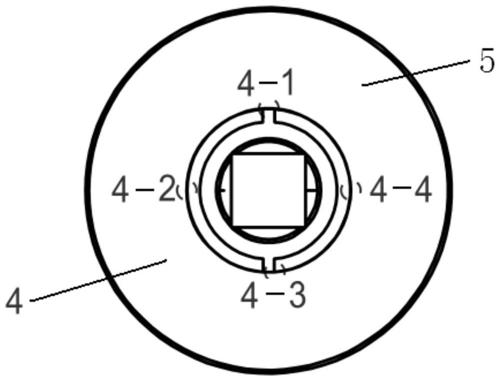
[0030] (1) Mounting of optical components: use gold-tin solder Sn / Au:80 / 20 to mount the chip on the heat sink, the thickness of the gold-tin solder is controlled between 3-6 microns, the solder is uniform, and the silver glue 84- 1 Mount the 45-degree all-reflection film on the plane optical path, the thickness of the silver glue is controlled between 3-6 microns, the glue is uniform, and the force direction is uniform, so that the thermal expansion coefficient of the optical path will remain the same without making the optical path Offset, after the laser chip emits light, the 45-degree all-reflection film rotates the light path by 45 degrees, and the vertical base is upward;

...


PUM

PropertyMeasurementUnit
Thicknessaaaaaaaaaa
Penetrationaaaaaaaaaa
Diameteraaaaaaaaaa

Abstract

The invention relates to the field of optical communication, in particular to a mounting and welding method for controlling tracking errors of coaxial optical devices. The mounting and welding methodfor controlling the tracking errors of the coaxial optical devices comprises the following steps of (1), mounting the optical devices; (2), mounting an isolator; (3), welding a pipe body; and (4), welding a plug pin. On the premise of ensuring correct mounting operation, a laser coupling welding process of the pipe body and the plug pin is adjusted, spot welding is adopted, each group of three welding spots are respectively welded by three welding guns, energy is uniformly distributed, stress pulling is consistent so that light path deviation cannot be caused, the welding spots welded by the plug pin are distributed in a plum blossom shape, welding symmetry can be increased, and sufficient stress release is guaranteed, so that performance of the devices is greatly improved, the power variation range along with the external environment temperature is reduced, the high-low temperature power errors of the coaxial devices are better controlled within the standard range, the rejection rateis reduced, the cost is low, and thus the mounting and welding method is suitable for batch production of coaxial products.

Description

Technical field [0001] The invention relates to the field of optical communication, and specifically relates to a mounting and welding method for controlling tracking errors of coaxial optical devices. Background technique [0002] With the rapid development of optical communications and the rapid acceleration in the 5G era, the reliability requirements for the core components of optical communications are becoming higher and higher, and optical devices are required to work at full temperature, that is, -45°C to 85°C. Changes in temperature require that the optical power be stabilized within a certain range to avoid errors in the communication system. [0003] The tracking error TE (Tracking Error) of the optical device refers to the ratio of the output power of the optical fiber under two different casing temperature conditions, which is used to measure the stability of the coupling efficiency of the device. In the production and manufacturing of optical devices, TE value is one ...

Claims


Application Information

Patent Timeline
IPC IPC(8): B23K26/21B23K26/70
CPCB23K26/21B23K26/702
Inventor 张彩崔琳武晓伟张培倪晓珍
Owner DALIAN CANGLONG OPTOELECTRONICS TECH
Why Eureka
Try Eureka