Microwave photon radar imaging system and method based on multi-channel time division dechirp reception

A microwave photon and multi-channel technology, applied in radio wave measurement system, electromagnetic wave re-radiation, radio wave reflection/re-radiation, etc. Power and signal-to-noise ratio deterioration and other issues

Active Publication Date: 2020-10-27
AEROSPACE INFORMATION RES INST CAS
View PDF9 Cites 2 Cited by
  • Summary
  • Abstract
  • Description
  • Claims
  • Application Information

AI Technical Summary

Problems solved by technology

However, with the increase of the detection width, the envelope of the echo signal and the reference signal is misaligned in the time domain, which leads to a decrease in the effective bandwidth of the deskewing process, thus sharply deteriorating the radar resolution and signal-to-noise ratio.
The contradiction between the width of de-skewing processing and the effective bandwidth limits the application of wide-width detection
In order to extend the detection range of the radar based on de-skewing reception, digital or analog delay is usually used for the reference signal, so that the delay corresponds to the echo delay of the target observation area, but this method can only change the detection range , cannot increase the radar detection width
In order to extend the detection width, the pulse width of the reference signal is usually larger than the echo signal, but this method needs to generate a reference signal with a larger bandwidth, and the bandwidth of the deskewing signal also increases with the increase of the detection width, and may even Larger than the bandwidth of the echo signal, it cannot effectively take advantage of the reduced sampling rate of the de-skewing reception system, so it cannot fundamentally solve the problem of the limited radar width of the de-skewing reception system

Method used


Image

  • Microwave photon radar imaging system and method based on multi-channel time division dechirp reception
  • Microwave photon radar imaging system and method based on multi-channel time division dechirp reception
  • Microwave photon radar imaging system and method based on multi-channel time division dechirp reception

Examples


Embodiment Construction

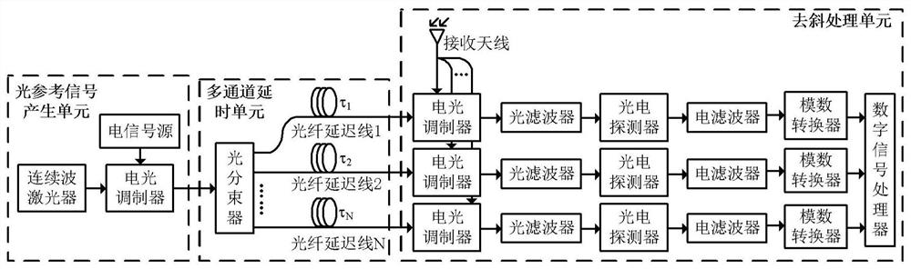
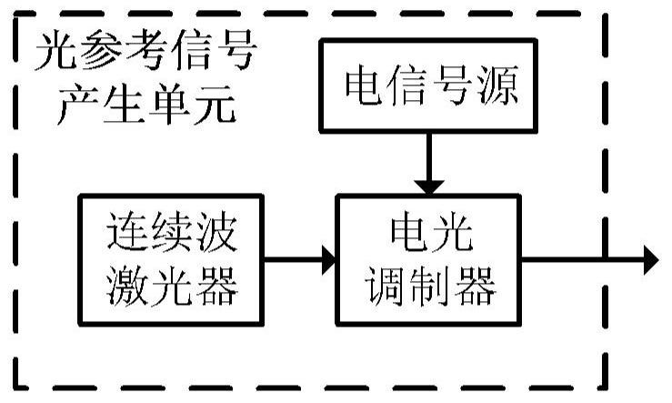
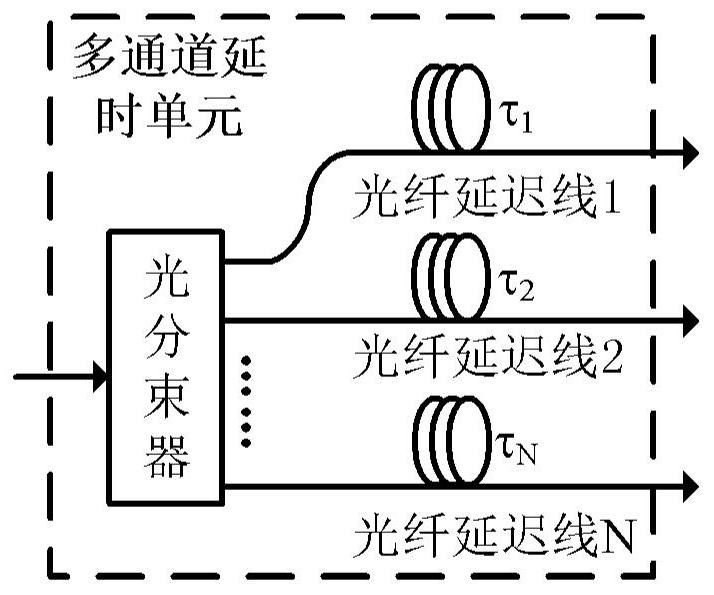
[0036] The invention discloses a large and wide microwave photon radar imaging system based on multi-channel time division multiplexing de-skewing receiving technology. Use the electrical signal source to generate coherent chirp electrical signals and chirp continuous wave electrical signals, where the chirp electrical signals are modulated onto the light and then the high-frequency broadband chirp signals are obtained by microwave photon frequency doubling technology as radar detection The signal is radiated into free space for detection; while the chirp continuous wave electrical signal is modulated onto the light as an optical reference signal. The optical reference signal passes through the multi-channel delay unit to form multiple optical reference signals with different delays, thereby forming multiple effective deskewing time windows within one receiving time window. After a delay, the optical reference signals of each channel are sent to the microwave photon deskewing ...


PUM


Abstract

The invention relates to a microwave photon radar signal receiving module. The module comprises an optical reference signal generating unit, a multi-channel delay unit and at least one dechirping processing unit; a signal output by the optical reference signal generating unit is transmitted to the multi-channel delay unit by an optical fiber; each path of optical fiber delay line of the multi-channel delay unit directly outputs the delayed optical signal to one dechirping processing unit for dechirping and subsequent algorithm processing. The invention further discloses a microwave photon radar imaging method based on multi-channel time division dechirp reception. According to the microwave photon radar signal receiving module and the method of the invention, the low-loss characteristic ofoptical fiber transmission is utilized; multi-channel copying and time delay are carried out on periodically repeated reference signals by virtue of a photonics technology, a plurality of effective dechirping processing time windows are formed in one receiving time window while signal coherence is ensured, and the detection breadth of a microwave photon radar based on the dechirping receiving technology is greatly expanded by virtue of limited hardware resources.

Description

technical field [0001] The invention relates to the technical field of radar imaging, in particular to a microwave photon radar imaging system and method based on multi-channel time division multiplexing de-skew receiving technology. Background technique [0002] Radar is a remote sensing device that uses electromagnetic waves to obtain information such as target position, velocity, and scattering characteristics. Compared with optical remote sensing methods, it has the advantage of being able to work all day and all day long. It has become an important detection and mapping in modern military and civilian fields. means. The development of modern radar requires the radar to provide more detailed target information to meet application requirements such as target recognition, which requires the radar to have a higher resolution. However, traditional electronic radar is difficult to realize the generation, transmission, control and processing of broadband signals due to the ba...

Claims


Application Information

Patent Timeline
Patent Type & Authority Applications(China)
IPC IPC(8): G01S13/26G01S13/89G01S17/26G01S17/89G01S7/4861G01S7/48G01S7/41G01S7/292
CPCG01S13/26G01S13/89G01S7/292G01S7/418G01S7/4861G01S7/4802G01S17/26G01S17/89
Inventor 李王哲莫镇玮
Owner AEROSPACE INFORMATION RES INST CAS
Why Eureka
Try Eureka