Motor encoder power supply method and system taking power from neutral point of output end of frequency converter

A technology of motor coding and power supply method, which is applied in the direction of output power conversion device, control system, irreversible AC power input conversion to DC power output, etc., which can solve the restrictions on the development of Wiegand effect self-powered encoders and the insulation performance of motors and sealing effects, the encoder is difficult to obtain power supply and other problems, to achieve the effect of protecting insulation and sealing, solving power shortage, and partially succinct

Active Publication Date: 2020-10-30
HUAZHONG UNIV OF SCI & TECH
View PDF9 Cites 2 Cited by
  • Summary
  • Abstract
  • Description
  • Claims
  • Application Information

AI Technical Summary

Problems solved by technology

However, since the energy source of electric energy is the kinetic energy of the rotating shaft, when the motor is at low speed or even stops, the kinetic energy of the rotating shaft is very small, and it is difficult for the encoder to obtain sufficient power supply, which leads to problems such as power failure. This defect restricts the Wiegand effect self-power supply development of encoders
[0005] Another solution is to take power from the three-phase drive bus at the motor input end. The power processing part of this solution is more complicated, and the insulation performance and sealing performance of the motor will be affected, which will destroy the balance of the power supply, so it is rarely used.

Method used


Image

  • Motor encoder power supply method and system taking power from neutral point of output end of frequency converter
  • Motor encoder power supply method and system taking power from neutral point of output end of frequency converter
  • Motor encoder power supply method and system taking power from neutral point of output end of frequency converter

Examples


Embodiment Construction

[0035] In order to make the object, technical solution and advantages of the present invention clearer, the present invention will be further described in detail below in conjunction with the accompanying drawings and embodiments. It should be understood that the specific embodiments described here are only used to explain the present invention, not to limit the present invention. In addition, the technical features involved in the various embodiments of the present invention described below can be combined with each other as long as they do not constitute a conflict with each other.

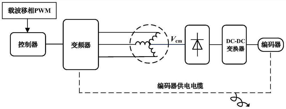
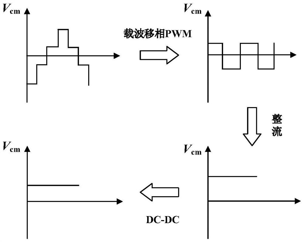
[0036] The embodiment of the present invention provides a motor encoder power supply method that takes power from the neutral point of the output end of the frequency converter. The method is as follows: figure 1 As shown, the change process of the common touch voltage during the power supply process is as follows figure 2 As shown, the method specifically includes the following steps:

[003...


PUM


Abstract

The invention discloses a motor encoder power supply method and system taking power from a neutral point of the output end of a frequency converter and belongs to the field of alternating current motors and drive control. The method comprises steps of improving a common-mode voltage waveform at a neutral point of a motor stator winding through a zero-free vector pulse width modulation method so that a common-mode voltage is converted into two levels from four levels; rectifying the suppressed common-mode voltage, and converting the two-level common-mode voltage into a direct-current voltage; and carrying out voltage conversion on the rectified direct current voltage, converting the direct current voltage into a voltage level required by encoder power supply, and then supplying power to theencoder. According to the method, a direct-current weak-current power supply cable led out for supplying power to the encoder is omitted so that the electrical connection between the motor and the frequency converter is simpler, and a problem of encoder power supply cable winding of motors such as industrial robots and the like in application occasions of multi-degree-of-freedom spatial motion isavoided, operation flexibility of the equipment is improved, meanwhile, a stable power supply can be provided for the encoder under different operation conditions of the motor.

Description

technical field [0001] The invention belongs to the field of AC motors and drive control, and more specifically relates to a motor encoder power supply method and system for taking power from a neutral point at an output end of a frequency converter. Background technique [0002] The servo system refers to the execution system that can quickly and accurately follow the position, speed, torque and other instructions issued by the control mechanism, also known as the servo system. The servo motor is the actuator of the servo system and the core component of the whole system. Its performance is directly related to the performance of the whole servo control system. Any high-performance servo motor contains a key component, the encoder. [0003] When the encoder is working, the diode emits light and detects and processes the signal, which is used to measure the real-time position and speed of the electrode rotor. To complete these tasks, an additional DC power supply cable is re...

Claims


Application Information

Patent Timeline
Patent Type & Authority Applications(China)
IPC IPC(8): H02K11/22H02M1/12H02M7/04H02P27/04
CPCH02K11/22H02M1/12H02M7/04H02P27/045H02M1/123
Inventor 刘自程樊隆源蒋栋
Owner HUAZHONG UNIV OF SCI & TECH
Why Eureka
Try Eureka