Power plant flue gas treatment system

A flue gas treatment system and flue gas technology are applied in the treatment of combustion products, combustion methods, indirect carbon dioxide emission reduction, etc., which can solve the problem of low temperature corrosion of air preheaters and blockage of ammonium hydrogen sulfate and high leakage risks of water-based heat exchangers. , high maintenance and operating costs, to achieve the effect of eliminating corrosion risks, facilitating on-site layout, and reducing maintenance and operating costs

Pending Publication Date: 2020-11-06
CHONGQING SHANGSHUN HEAT TRANSFER EQUIP
View PDF14 Cites 1 Cited by
  • Summary
  • Abstract
  • Description
  • Claims
  • Application Information

AI Technical Summary

Problems solved by technology

As mentioned above, although these systems can achieve waste heat reuse to a certain extent, they cannot systematically solve a series of problems such as low-temperature corrosion of the air preheater and ammonium bisulfate clogging. There are problems such as wear and tear, and the water medium heat exchanger also has problems such as high risk of leakage, high maintenance and operation costs

Method used


Image

  • Power plant flue gas treatment system
  • Power plant flue gas treatment system

Examples


Embodiment 1

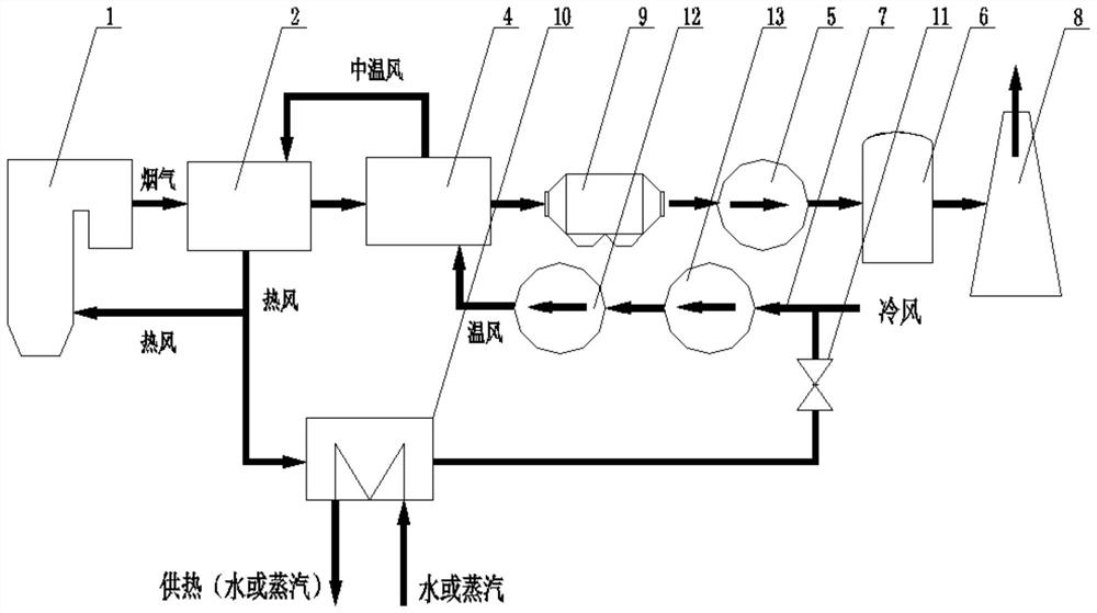
[0019] A power plant flue gas treatment system, such as figure 1 As shown, it includes a flue path mainly composed of a boiler 1, a rotary air preheater 2, a flue gas heater 4, an induced draft fan 5, a desulfurization tower 6 and a chimney 8, and the flue gas heater 4 adopts As the cooling medium, the air is introduced into the flue gas heater 4 and exchanges heat with the flue gas flowing through the flue gas heater 4, and the medium-temperature wind obtained from the heat exchange is introduced into the rotary air preheater 2, and the medium-temperature wind and the flow The flue gas from the rotary air preheater 2 performs heat exchange, the first part of the hot air obtained from the heat exchange is introduced into the boiler 1 as a heat source, and the second part of the hot air obtained from the heat exchange is cooled by heat exchange and used as a part of the flue gas heater 4 cold medium.

[0020] Among them, the air volume used for the flue gas heater 4 is 10%-20%...

Embodiment 2

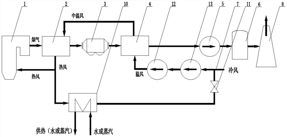
[0028] A power plant flue gas treatment system, such as figure 2 As shown, it includes a flue path mainly composed of a boiler 1, a rotary air preheater 2, a flue gas heater 4, an induced draft fan 5, a desulfurization tower 6 and a chimney 8, and the flue gas heater 4 adopts As the cooling medium, the air is introduced into the flue gas heater 4 and exchanges heat with the flue gas flowing through the flue gas heater 4, and the medium-temperature wind obtained from the heat exchange is introduced into the rotary air preheater 2, and the medium-temperature wind and the flow The flue gas from the rotary air preheater 2 performs heat exchange, the first part of the hot air obtained from the heat exchange is introduced into the boiler 1 as a heat source, and the second part of the hot air obtained from the heat exchange is cooled by heat exchange and used as a part of the flue gas heater 4 cold medium.

[0029] Among them, the air volume used for the flue gas heater 4 is 10%-20...


PUM


Abstract

The invention provides a power plant flue gas treatment system. The power plant flue gas treatment system comprises a flue gas path which is mainly formed by connecting a boiler, a rotary air preheater, a flue gas air heater, an induced draft fan, a desulfurization tower and a chimney in sequence. The flue gas air heater adopts air as a cold medium, the air is introduced into the flue gas air heater and exchanges heat with flue gas flowing through the flue gas air heater, medium-temperature air obtained through heat exchange is introduced into the rotary air preheater and exchanges heat with flue gas flowing through the rotary air preheater, a first part of hot air obtained through heat exchange is introduced into the boiler to serve as a heat source, and a second part of hot air obtainedthrough heat exchange is cooled by heat exchange and then is recycled as part of the cold medium of the flue gas air heater. The power plant flue gas treatment system completely solves the problems oflow-temperature corrosion and ammonium bisulfate blockage of the rotary air preheater, can ensure the long-term safe and economical operation of the air preheater and reduce the maintenance and operation cost, and has high controllability and operation flexibility.

Description

technical field [0001] The invention relates to a coal-fired boiler system of a power plant, in particular to a flue gas treatment system of a power plant. Background technique [0002] After the ultra-clean emission transformation, the air preheater of the power plant generally has a series of problems such as low-temperature corrosion, ammonium bisulfate clogging, and high exhaust gas temperature, and the heat loss of the exhaust gas also accounts for a large proportion. Problems, and to make full use of this part of energy, it is necessary to use special technology to solve these problems systematically. In order to realize boiler waste heat recovery, various devices and systems have been developed. The boiler flue gas waste heat recovery system as disclosed in CN205807452U includes: an air preheater installed at the tail of the boiler; a temperature sensor arranged on the exhaust pipe and at the outlet of the air preheater; through the exhaust pipe and The waste heat r...

Claims


Application Information

Patent Timeline
Patent Type & Authority Applications(China)
IPC IPC(8): F23L15/00F23J15/02
CPCF23L15/00F23J15/02F23J15/025F23J2215/20F23J2217/102Y02E20/34
Inventor 王键
Owner CHONGQING SHANGSHUN HEAT TRANSFER EQUIP
Why Eureka
Try Eureka