
An energy storage type DC power buffer system

A DC power and buffer system technology, applied in vehicle energy storage, DC network circuit devices, information technology support systems, etc., can solve the problems of few adjustable parameters, limited output power, limited energy recovery efficiency, etc. The effect of working time, reducing size and weight, optimizing design performance

Active Publication Date: 2022-07-08
鲁逢源
View PDF7 Cites 0 Cited by
  • Summary
  • Abstract
  • Description
  • Claims
  • Application Information

AI Technical Summary

Problems solved by technology

[0003] 1. The output power of wind power, photovoltaic and other devices is limited and unstable, and it is difficult to directly support the continuous operation of motors and other equipment
For example, the rated power of ordinary monocrystalline silicon solar cells is 100W, which must be achieved under good lighting conditions and appropriate output loads. Whether it is changes in lighting conditions or load characteristics, the output voltage of solar cells will be affected. Such voltage fluctuations are very unfavorable for post-stage equipment with certain power requirements. Usually, the rated power of 100W cannot be fully utilized due to impedance mismatch, which reduces the economic benefits of new energy and forces the system to invest in more redundant power design to deal with it. Disturbances caused by environmental changes
Wind power usually does not directly drive loads, but its power output also fluctuates with changes in the environment, which is difficult to overcome without special buffer measures
[0004] 2. Mobile platforms such as unmanned vehicles and robots often require extremely high burst power input during the execution of tasks. 1. When electric braking is suddenly implemented (a special case of stalled rotor), the current required is usually several times or even ten times the power required for smooth operation. The power required in the environment is small, so it is not worth the loss to equip a huge power supply device (such as a larger battery pack) to meet the instantaneous load demand at the expense of portability, safety and economy, and the limited power supply capacity is only It can force the motion system to reduce the speed and range of motion to save power, and compromise performance as a last resort
[0005] 3. For inductive loads such as electric motors, if photovoltaic batteries are used as energy sources, reverse energy conversion cannot be implemented, which will cause nowhere to release the induced current generated during deceleration or braking, thereby increasing the voltage on the input line, which may cause damage to the equipment , and when used with batteries and other energy sources that can withstand a certain reverse current, the charging current that the charging circuit can withstand usually has a rated value, which needs to be determined in advance by setting or adjusting circuit parameters. The induction generated during braking If the current exceeds the maximum charging current, it will not be fully absorbed and the energy recovery efficiency is relatively limited
In addition, when using a dedicated current-limiting charging circuit, it is necessary to implement a set of switching topologies so that the input power is disconnected at the moment of deceleration and braking of the motor, and then the charging circuit is connected. When the power supply is restored from the charging state, the reverse switching is required, which increases the system complexity
[0006] 4. Most of the battery charging management system, solar battery power supply system, measurement and protection system and the real load electrical device in the application project of multiple energy combination power supply are special-purpose and poor in versatility The status quo, different manufacturers split the design of several independent equipment
When these devices are integrated into related applications, there are usually disadvantages such as complicated connection, inconvenient unified coordination, no or few communication functions, few adjustable parameters, and working parameters that cannot be changed remotely and in real time, making the integration of the entire application product , the degree of automation and intelligence is limited

Method used


Image

  • An energy storage type DC power buffer system
  • An energy storage type DC power buffer system
  • An energy storage type DC power buffer system

Examples


Embodiment Construction

[0041] In the description of the present invention, it should be noted that the terms "installed", "connected" and "connected" should be understood in a broad sense, unless otherwise expressly specified and limited, for example, it may be a fixed connection or a detachable connection Connection, or integral connection; can be mechanical connection, can also be electrical connection; can be directly connected, can also be indirectly connected through an intermediate medium, can be internal communication between two elements. For those of ordinary skill in the art, the specific meanings of the above terms in the present invention can be understood in specific situations.

[0042] Various structural schematic diagrams according to the disclosed embodiments of the present invention are shown in the accompanying drawings. The figures are not to scale, some details have been exaggerated for clarity, and some details may have been omitted. The shapes of various regions and layers sh...


PUM


Abstract

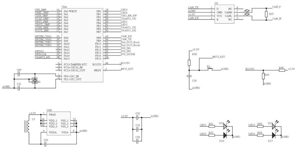
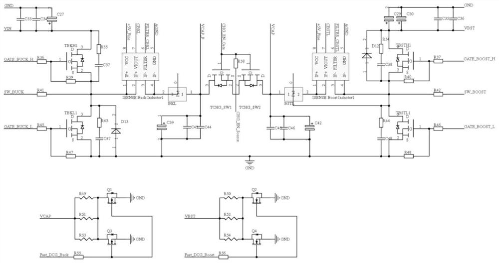
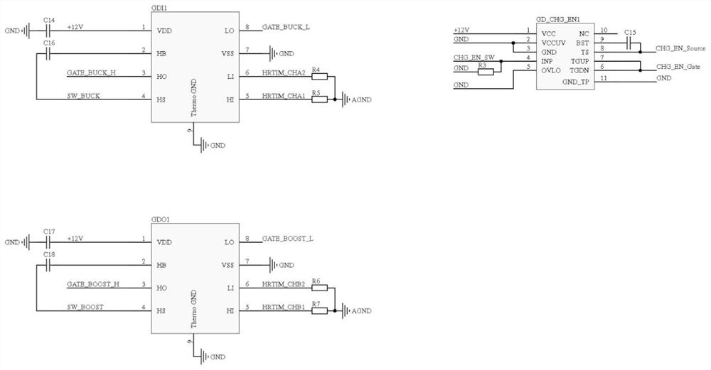
The invention discloses an energy storage type DC power buffer system. The main power input is divided into two paths, one path is connected to a power stage circuit and a measurement sampling circuit, and the other path is connected to a power path switching element, the power stage circuit and the measurement sampling circuit and the power path switching The component connection is used for the controlled switching of the two-way power supply; the power stage circuit and the measurement sampling circuit are divided into three channels, one of which is connected to the main control unit through the voltage and current measurement circuit, and the second is connected to the main control unit through the transistor gate drive circuit. In order to send the gate drive signal and timing control signal to the main control unit, the third circuit is connected to the main control unit through the energy storage element and the overvoltage rapid discharge element in turn, and is used to send the logic level signal to the main control unit. The control unit is connected to the power path switching element for outputting the load. The invention has high integration degree and simple structure, and can effectively provide the buffer function in the direct current power supply system to cope with the sudden change of load power.

Description

technical field [0001] The invention belongs to the technical field of new energy and energy saving, and in particular relates to an energy storage type DC power buffer system. Background technique [0002] With the large-scale application of electric drive technology in vehicles, industrial equipment, robots and other fields and the continuous popularization of new energy technologies such as solar energy and wind energy, some existing methods such as disposable chemical batteries, storage batteries, solar cells, and wind power generation rely on DC power. The driver system has the following problems: [0003] 1. The output power of wind power, photovoltaic and other devices is limited and unstable, and it is difficult to directly support the continuous operation of electric motors and other equipment. For example, the rated power of an ordinary monocrystalline silicon solar cell is 100W, which can only be achieved under good lighting conditions and when the appropriate ou...

Claims


Application Information

Patent Timeline
Patent Type & Authority Patents(China)
IPC IPC(8): H02J1/00H02J1/14H02J9/06
CPCH02J1/00H02J1/14H02J9/061H02J9/068Y04S20/20
Inventor 鲁逢源
Owner 鲁逢源
Learn More