
Cutting equipment for steel pipe processing

A technology of cutting equipment and steel pipes, which is applied in the field of steel pipe processing, can solve the problems of staff burns, increased friction between blades and steel pipes, and affecting cutting accuracy, and achieves the effects of improving environmental protection, improving safety, and saving resources

Inactive Publication Date: 2020-11-24
南京宜泽新材料科技有限公司
View PDF4 Cites 4 Cited by
  • Summary
  • Abstract
  • Description
  • Claims
  • Application Information

AI Technical Summary

Problems solved by technology

[0003] When the existing cutting equipment is cutting, it is easy to generate more high-temperature debris. If the high-temperature debris splashes on the staff, it is easy to cause the staff to be scalded, which reduces the safety of the existing cutting equipment. Not only that, the existing When the advanced cutting equipment is working, debris is easy to adhere to the blade, thereby increasing the friction between the blade and the steel pipe, affecting the cutting work, thereby affecting the cutting accuracy, and reducing the practicability of the existing cutting equipment

Method used


Image

  • Cutting equipment for steel pipe processing
  • Cutting equipment for steel pipe processing
  • Cutting equipment for steel pipe processing

Examples


Embodiment Construction

[0030] The present invention is described in further detail now in conjunction with accompanying drawing. These drawings are all simplified schematic diagrams, which only illustrate the basic structure of the present invention in a schematic manner, so they only show the configurations related to the present invention.

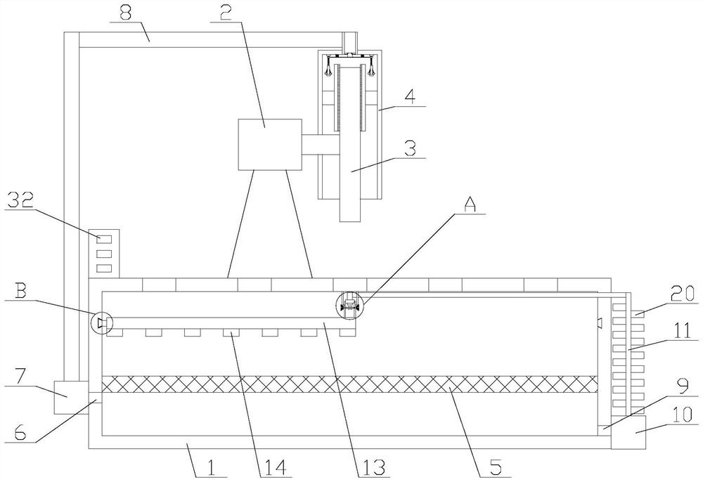
[0031] Such as figure 1 As shown, a cutting device for steel pipe processing includes a workbench 1, a motor 2, a protective cover 4 and a blade 3, the motor 2 is fixed above the workbench 1, and the protective cover 4 is fixedly connected to the motor 2 , one side of the protective cover 4 is provided with a through hole, the output shaft of the motor 2 is arranged inside the protective cover 4 through the through hole, the output shaft of the motor 2 is fixedly connected with the blade 3, and the blade 3 It is arranged inside the protective cover 4, a PLC is arranged in the workbench 1, and the motor 2 is electrically connected to the PLC, and also includes...


PUM


Abstract

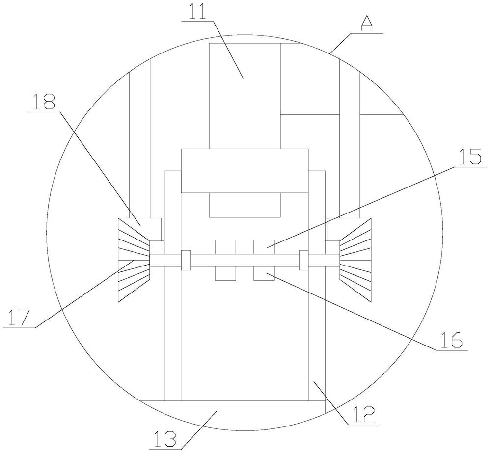
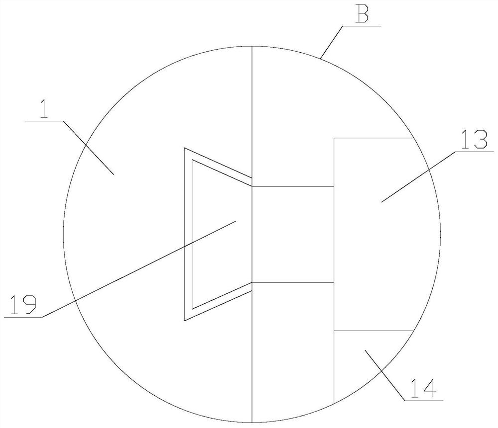
The invention relates to cutting equipment for steel pipe processing. The cutting equipmentcomprises a workbench, a motor, a protective cover, a blade, a collection mechanism and a cleaning mechanism,wherein the collection mechanism comprises a filter screen, an air suction assembly and a cooling assembly; the air suction assembly comprises an air suction pump, an air inlet pipe and an air outletpipe; the cooling assembly comprises a water pumping unit, a connecting pipe, a spraying pipe, a first bearing, a first bevel gear, a power unit, two fixing rods and two second bevel gears; the cleaning mechanism comprises a driving assembly, two knocking assemblies and two cleaning assemblies, and each cleaning assembly comprises a fixing block and a cleaning plate. According to the cutting equipment for steel pipe processing, the function of collecting high-temperature chips is achieved by the collection mechanism, the high-temperature chips are prevented from splashing on workers, and safety and environmental protection of the equipment are improved; and the blade can be cleaned by the cleaning mechanism, so that the influence on cutting due to the fact that the chips generated duringcutting adhere to the blade is prevented.

Description

technical field [0001] The invention relates to the field of steel pipe processing, in particular to a cutting device for steel pipe processing. Background technique [0002] Steel pipe cutting machine, mechanical equipment. It is widely used in petroleum, chemical industry, electric power, natural gas, metallurgy, shipbuilding, boiler, pharmaceutical, water treatment and other industries, as well as pipeline installation engineering and pipeline maintenance of new projects. [0003] When the existing cutting equipment is cutting, it is easy to generate more high-temperature debris. If the high-temperature debris splashes on the staff, it is easy to cause the staff to be scalded, which reduces the safety of the existing cutting equipment. Not only that, the existing When the advanced cutting equipment is working, debris is easy to adhere to the blade, thereby increasing the friction between the blade and the steel pipe, affecting the cutting work, thereby affecting the cutt...

Claims


Application Information

Patent Timeline
Patent Type & Authority Applications(China)
IPC IPC(8): B23Q11/00B23Q11/02F25D1/02F28F1/36
CPCB23Q11/005B23Q11/0078B23Q11/02F25D1/02F28F1/36
Inventor 平克宇
Owner 南京宜泽新材料科技有限公司
Learn More