
Wave energy conversion semi-physical simulation test bed

A semi-physical simulation, wave energy technology, applied in the direction of fluid dynamics test, conversion sensor output, machine/structural component testing, etc., can solve the problems of accuracy error, large model test cost, etc. The effect of reducing test cost and quick response

Pending Publication Date: 2020-12-01
HEFEI UNIV OF TECH
View PDF11 Cites 2 Cited by
  • Summary
  • Abstract
  • Description
  • Claims
  • Application Information

AI Technical Summary

Problems solved by technology

[0004] The purpose of the present invention is to make up for the defects of the prior art, to provide a semi-physical simulation test bed for wave energy conversion, which can reproduce the movement of the float in the ocean in real time in the absence of laboratory pools and sea trials, and drive wave energy The conversion system converts wave energy into electrical energy or desalinates seawater, and completes the performance test of the wave energy conversion device. The semi-physical simulation test bench combines the actual wave energy conversion system with the float motion simulation system under the action of waves, overcoming the large model test. The huge cost and small model test can not truly reflect the actual situation of the prototype, and at the same time avoid the error caused by the accuracy of the model to the calculation result of the computer simulation

Method used


Image

  • Wave energy conversion semi-physical simulation test bed
  • Wave energy conversion semi-physical simulation test bed
  • Wave energy conversion semi-physical simulation test bed

Examples


Embodiment Construction

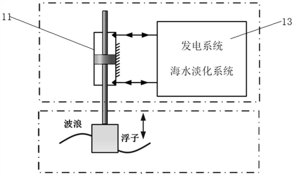
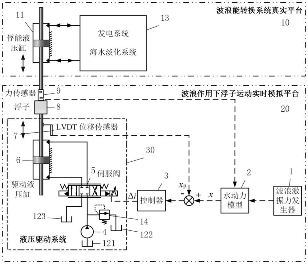
[0031] Such as figure 1 , 2 As shown, a semi-physical simulation test bed for wave energy conversion includes a real platform 10 for the wave energy conversion system and a real-time simulation platform 20 for floater motion under the action of waves. The real platform 10 for the wave energy conversion system includes an energy capture hydraulic cylinder 11, a wave Energy generation system or seawater desalination system 13, the real-time simulation platform 20 of the float movement under the action of waves includes a wave excitation force generator 1, a hydrodynamic model 2, a controller 3, a float 8, a force sensor 9, and a hydraulic drive system 30, The hydraulic drive system 30 includes a hydraulic pump 4 , an overflow valve 14 , an oil tank, an electro-hydraulic servo valve 5 , a driving hydraulic cylinder 6 , and an LVDT displacement sensor 7 .

[0032] Hydrodynamic model 2 is a mathematical model that reflects the interaction between the buoy and the waves in the ocea...


PUM


Abstract

The invention discloses a wave energy conversion semi-physical simulation test bed. The wave excitation force and the acting force of an energy harvesting hydraulic cylinder on a floater are jointly input into a floater hydrodynamic model; the expected displacement of the floater is calculated; the actual displacement of a driving hydraulic cylinder is compared with the expected displacement of the floater; a calculated deviation signal acts on an electro-hydraulic servo valve through the controller to control a valve core of the electro-hydraulic servo valve to act; the flow of the oil liquidwhich is output from a hydraulic pump to enter the driving hydraulic cylinder is controlled; the driving hydraulic cylinder drives the floater to move; a piston rod of the energy harvesting hydrauliccylinder is further pushed to move; a high-pressure transmission medium is output to drive a wave energy power generation system or a sea water desalination system to do work to convert pressure energy of the high-pressure transmission medium into electric energy or drive a reverse osmosis membrane to work to realize sea water desalination; the movement of the floater in actual ocean waves can bereproduced under the conditions that no laboratory water pool exists and sea tests cannot be conducted, and the wave energy conversion system is driven to convert wave energy into electric energy orconduct sea water desalination.

Description

technical field [0001] The invention relates to the technical field of wave energy conversion, in particular to a semi-physical simulation test bed for wave energy conversion. Background technique [0002] Wave energy has a large reserve and high energy density, and it is a clean and renewable energy source. my country has a long coastline and many islands. The development and utilization of wave energy can effectively solve the energy supply problem of islands and offshore platforms. At the same time, it has important economic value and social significance for alleviating my country's energy pressure, optimizing energy structure and improving environmental pollution. At present, most wave energy conversion devices are still in the stage of laboratory research, and only a few devices have entered sea trials. The wave energy conversion device must not only convert violent wave energy into stable and usable energy in the sea area where it is deployed, but also adapt to harsh ...

Claims


Application Information

Patent Timeline
IPC IPC(8): G01M10/00G01D5/22
CPCG01M10/00G01D5/2291
Inventor 刘常海曾亿山胡敏刘旺黄河高文智陈建
Owner HEFEI UNIV OF TECH
Features
  • Generate Ideas
  • Intellectual Property
  • Life Sciences
  • Materials
  • Tech Scout
  • Unparalleled Data Quality
  • Higher Quality Content
  • 60% Fewer Hallucinations
Learn More