

Catalyst
A catalyst and microstructuring technology, applied in the direction of catalyst activation/preparation, physical/chemical process catalyst, metal/metal oxide/metal hydroxide catalyst, etc., can solve loss of surface area, loss of specific activity of electrocatalyst, particle sintering Surface roughness loss etc.
- Summary
- Abstract
- Description
- Claims
- Application Information
AI Technical Summary
Problems solved by technology
Method used
Image

Examples
preparation example A
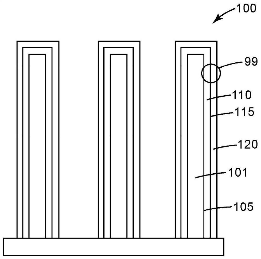
[0098] Using microstructured catalyst transfer substrates (or MCTS) as described in U.S. Patent 6,136,412 (Spiewak et al.) 5039561 (Debe) (also incorporated herein by reference) for the preparation of microstructured whiskers for use as catalyst supports. The perylene red pigment (i.e., N,N'-bis(3,5-xylyl)perylene-3,4:9,10-bis(dicarboximide)) Pigment Red 149, also known as "PR149 ", available from Clariant, Charlotte, NC) by sublimation vacuum deposition onto MCTS with a nominal thickness of 200 nm and then annealed. After deposition and annealing, a highly oriented crystal structure is formed: its aspect ratio is very large, its controllable length is about 0.5 micron to 2 microns, its width is about 0.03 micron to 0.05 micron, and its domain density is about 30 whiskers per square micron , the structure is oriented substantially perpendicular to its underlying substrate.
Embodiment 1
[0125] The Example 1 catalyst was prepared and characterized as described for Comparative Example A, except that a layer of tantalum was deposited prior to Pt deposition, the Pt deposition conditions were modified to vary the Pt loading, and the catalyst was conditioned prior to assembly into a MEA. thermal annealing.
[0126] The NSTF catalyst layer, Preparation A, was prepared by sequentially sputtering the catalyst film onto the microstructured whisker layer using a DC-magnetron sputtering process. A vacuum sputter deposition system was used with a typical Ar sputter gas pressure of about 3.3 mTorr (0.44 Pa) and 5 inch by 15 inch (12.7 cm by 38.1 cm) rectangular Pt and Ta sputter targets. System base pressure is usually 2.5×10 -5 Torr (0.0033Pa), the background gas usually measured is water vapor. The coating was deposited by using ultra-high purity Ar as the sputtering gas.
[0127] A single Ta layer with a planar equivalent thickness of about 0.5 nm was first deposited...
Embodiment 2-7
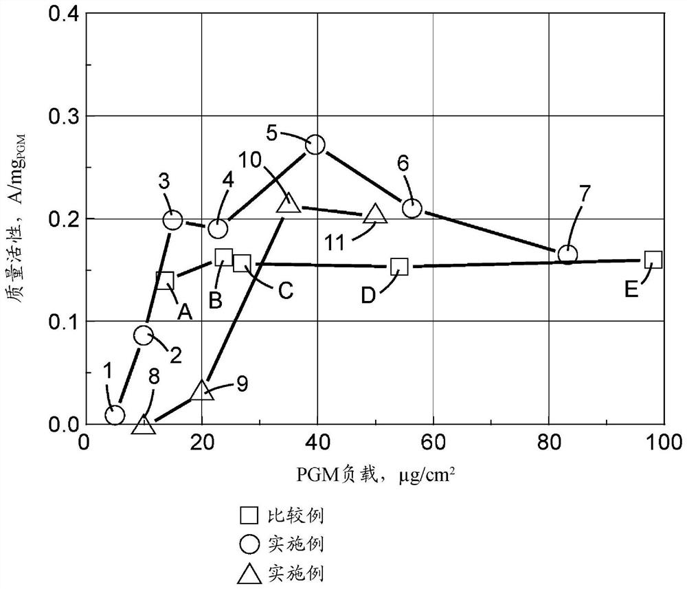
[0130] Examples 2 to 7 were prepared and characterized as described for Example 1, except that the Pt deposition process was modified such that the Pt areal loading was about 10 micrograms / cm each 2 , 15 micrograms / cm 2 , 20 micrograms / cm 2 , 40 micrograms / cm 2 , 50 micrograms / cm 2 and 78 μg / cm 2 , and were additionally characterized as described below. The results are provided in Table 5 above.
[0131]After completing the characterization of the fuel cell, the catalyst of Example 2 was characterized by transmission electron microscopy (TEM) and energy dispersive X-ray spectroscopy (EDS). The Example 4 catalyst was characterized by TEM and EDS after deposition of the catalyst metal onto the microstructured whiskers, after thermal annealing of the catalyst, and after fuel cell characterization. The Pt:Ta atomic ratios are summarized in Table 6 below. The Pt:Ta atomic ratio of Example 2 was 1.09. The Pt:Ta atomic ratio of the catalyst of Example 4 ranged between 2.17 an...
PUM
| Property | Measurement | Unit |
|---|---|---|
| thickness | aaaaa | aaaaa |
| thickness | aaaaa | aaaaa |
| particle size | aaaaa | aaaaa |
Abstract
Description
Claims
Application Information