Tubular ammonia decomposition reactor
A technology of ammonia decomposition and reactor, which is applied in the field of ammonia decomposition and hydrogen production, can solve the problems of complex structure of ammonia decomposition device and high equipment operation cost, and achieve the effects of low energy consumption, reduction of equipment cost and simplification of device structure
- Summary
- Abstract
- Description
- Claims
- Application Information
AI Technical Summary
Problems solved by technology
Method used
Image

Examples
Embodiment 1
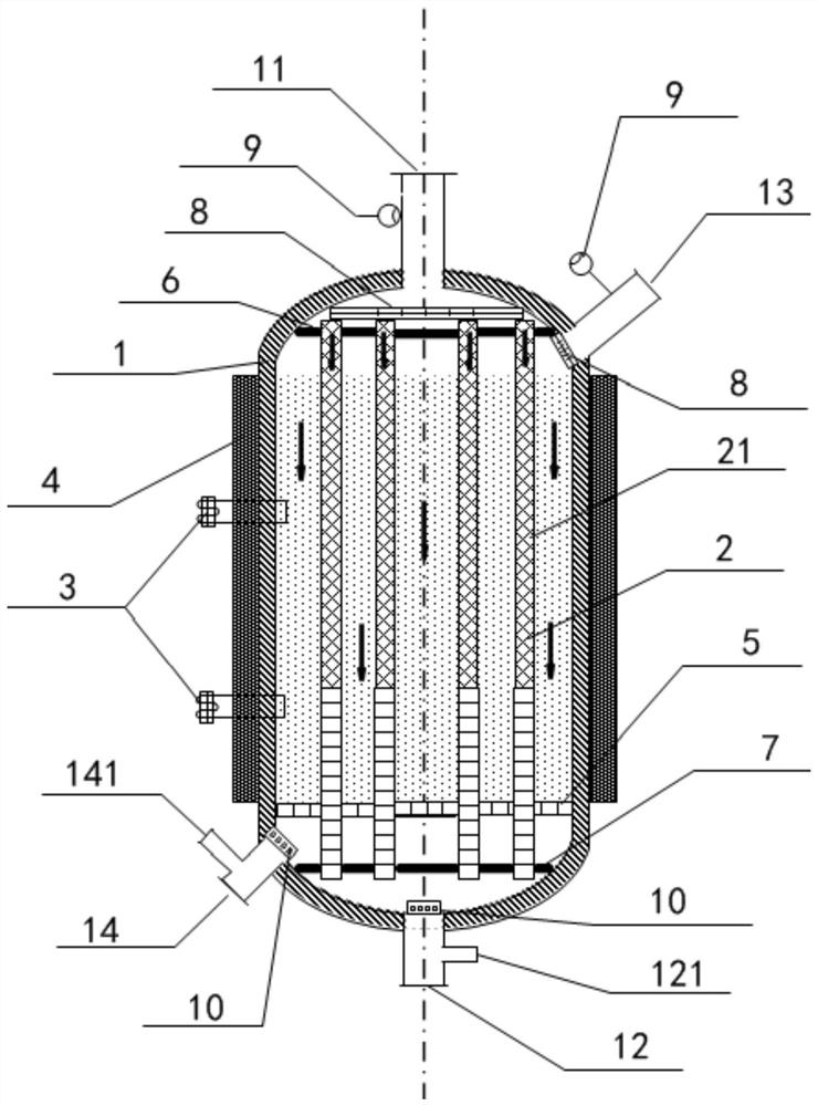
[0045] Such as figure 1 As shown, the present embodiment provides a tubular ammonia decomposition reactor, comprising:
[0046] The sleeve 1 includes a first air inlet 11 and a first air outlet 12, and a second air inlet 13 and a second air outlet 14 oppositely arranged;
[0047] The inner tube 2 is arranged inside the sleeve 1, the inner tube 2 is filled with an ammonia decomposition catalyst, the gap between the inner tube 2 and the sleeve 1 is filled with a catalytic combustion catalyst, and one end of the inner tube 2 communicates with the first air inlet 11, The opposite end communicates with the first air outlet 12;
[0048] The second air inlet 13 is suitable for communicating with fuel gas, and the fuel gas is suitable for exothermic reaction with the catalytic combustion catalyst.
[0049] In the above-mentioned tubular ammonia decomposition reactor, the fuel gas enters the gap between the inner pipe 2 and the sleeve 1 from the second air inlet 13, generates heat un...
Embodiment 2
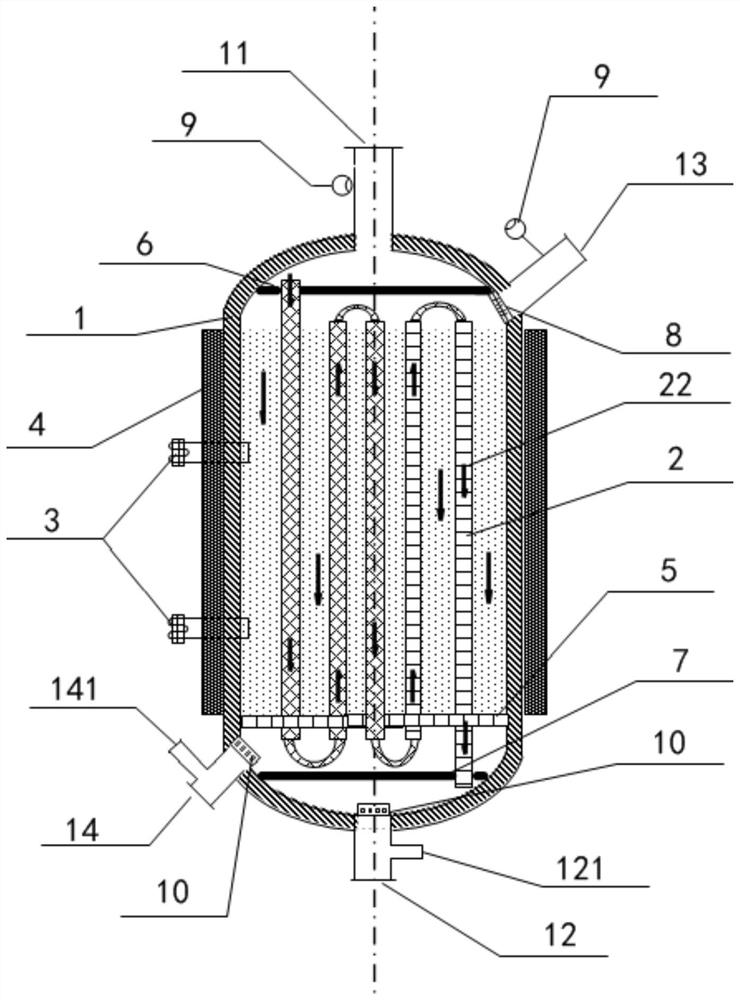
[0064] This embodiment provides a tubular ammonia decomposition reactor, which differs from the tubular ammonia decomposition reactor provided in Example 1 in that: figure 2 As shown, the inner pipe 2 is five pipes arranged in series, the end of the inner pipe 2 near the first air inlet 11 runs through the upper partition 6, and the end of the inner pipe 2 near the first air outlet 12 runs through the lower partition 7 above, so that the fuel gas enters the pipeline and the ammonia gas enters the gap between the pipeline and the sleeve 1 to ensure that the two chemical reactions do not affect each other. It should be understood that the number of second pipes 22 includes but is not limited to five, and the application does not limit the shapes of the sleeve 1, the upper partition 6 and the lower partition 7, and those skilled in the art can choose according to needs .
Embodiment 3
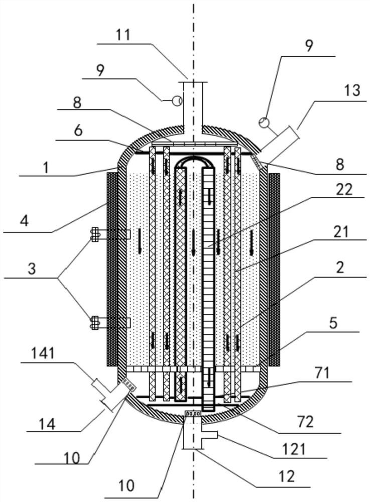
[0066] This embodiment provides a tubular ammonia decomposition reactor, which differs from the tubular ammonia decomposition reactor provided in Example 1 in that: image 3 As shown, the inner tube 2 includes:
[0067] 4 first pipelines 21 connected in parallel;
[0068] The gas outlet mixing chamber is arranged between the catalytic combustion catalyst and the first gas outlet 12, and the gas outlet of the first pipeline 21 enters the gas outlet mixing chamber;
[0069] Two second pipes 22 connected in series, one end enters the gas outlet mixing chamber, the other end extends to the area between the gas outlet mixing chamber and the first gas outlet 12, and the part between the two ends is embedded in the catalytic combustion catalyst.
[0070]Specifically, the lower partition 7 includes a first lower partition 71 and a second lower partition 72, wherein the first lower partition 71 is arranged close to the grid plate 5, and the second lower partition 72 is arranged near t...
PUM
 Abstract
Description
Claims
Application Information
 - R&D
- Intellectual Property
- Life Sciences
- Materials
- Tech Scout
- Unparalleled Data Quality
- Higher Quality Content
- 60% Fewer Hallucinations
Browse by: Latest US Patents, China's latest patents, Technical Efficacy Thesaurus, Application Domain, Technology Topic, Popular Technical Reports.
© 2025 PatSnap. All rights reserved.Legal|Privacy policy|Modern Slavery Act Transparency Statement|Sitemap|About US| Contact US: help@patsnap.com