Infrared window anti-reflection protection structure and preparation method thereof

An anti-reflection protection, infrared window technology, applied in the direction of ion implantation plating, gaseous chemical plating, superimposed layer plating, etc., can solve the problems of reducing film stress, depositing diamond-like film, etc. , The structure is simple, the effect of improving the optical transmittance

Pending Publication Date: 2020-12-15
昆明奥夫特光电技术有限公司
View PDF0 Cites 1 Cited by
  • Summary
  • Abstract
  • Description
  • Claims
  • Application Information

AI Technical Summary

Problems solved by technology

[0003] Aiming at the deficiencies of the prior art, the present invention provides an infrared window anti-reflection protection structure and a preparation method thereof. The germanium-arsenic-selenium layer is used as the only intermediate layer between the diamond-like layer and the base layer, which increases the optical transmission of the window on the one hand. On the other hand, it reduces the stress between the film layers and solves the problem that the diamond-like film cannot be deposited on the chalcogenide material.

Method used


Image

  • Infrared window anti-reflection protection structure and preparation method thereof

Examples


Embodiment 1

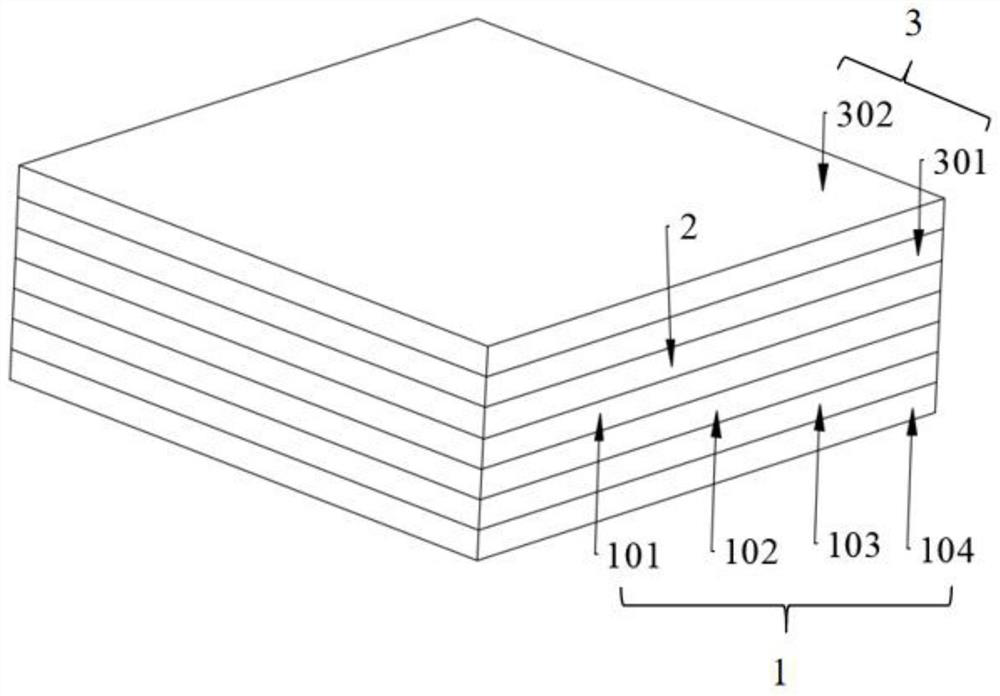
[0027] An infrared window anti-reflection protection structure, the structure includes an anti-reflection layer 1, a base 2 and a protective layer 3, the anti-reflection layer 1 is attached to one side of the base 2, and the protective layer 3 is attached to the other side;

[0028] The anti-reflection layer 1 sequentially includes a first germanium layer 101, a first zinc sulfide layer 102, a second germanium layer 103 and a second zinc sulfide layer 104 starting from the substrate 2;

[0029] The protection layer 3 includes a GeAsSe layer 301 and a diamond-like carbon layer 302 sequentially from the substrate 2 .

[0030] Specifically, the substrate 2 is chalcogenide glass IRG206.

[0031] Specifically, the thickness of the first germanium layer 101 is 100 nm; the thickness of the first zinc sulfide layer 102 is 2200 nm; the thickness of the second germanium layer 103 is 50 nm; the thickness of the second zinc sulfide layer 104 is 1100 nm.

[0032] Specifically, the thickne...

Embodiment 2

[0039] The difference with Embodiment 1 is:

[0040] Specifically, the substrate 2 is germanium glass.

[0041] Specifically, the thickness of the first germanium layer 101 is 500 nm; the thickness of the first zinc sulfide layer 102 is 500 nm; the thickness of the second germanium layer 103 is 100 nm; the thickness of the second zinc sulfide layer 104 is 500 nm.

[0042] Specifically, the thickness of the GeAsSe layer 301 is 500 nm; the thickness of the DLC layer 302 is 500 nm.

Embodiment 3

[0044] The difference with Embodiment 1 is:

[0045] Specifically, the substrate 2 is silicon glass.

[0046] Specifically, the thickness of the first germanium layer 101 is 800nm; the thickness of the first zinc sulfide layer 102 is 1800nm; the thickness of the second germanium layer 103 is 200nm; the thickness of the second zinc sulfide layer 104 is 800nm.

[0047] Specifically, the thickness of the GeAsSe layer 301 is 800 nm; the thickness of the DLC layer 302 is 1000 nm.


PUM

PropertyMeasurementUnit
thicknessaaaaaaaaaa
thicknessaaaaaaaaaa
thicknessaaaaaaaaaa

Abstract

The invention relates to the technical field of optical films, in particular to an infrared window anti-reflection protection structure and a preparation method thereof. The structure comprises an anti-reflection layer, a substrate and a protection layer, wherein an anti-reflection layer is attached to one side of the substrate, and a protection layer is attached to the other side of the substrate; the anti-reflection layer sequentially comprises a first germanium layer, a first zinc sulfide layer, a second germanium layer and a second zinc sulfide layer from the substrate; and the protectionlayer sequentially comprises a germanium- arsenic-selenium layer and a diamond-like carbon layer from the substrate. The infrared window anti-reflection protection structure and the preparation methodthereof are provided, the germanium-arsenic-selenium layer serves as a unique middle layer between the diamond-like carbon layer and a substrate layer, on one hand, the optical permeability of a window is improved, and on the other hand, the stress between film layers is reduced, and the problem that a diamond-like carbon film cannot be deposited on a sulfur group material is solved.

Description

technical field [0001] The invention relates to the technical field of optical thin films, in particular to an infrared window antireflection protection structure and a preparation method thereof. Background technique [0002] In recent years, with the development of infrared technology, infrared has very important applications in military, industry, transportation and other aspects. Infrared technology continues to advance and advances the development of infrared materials, especially materials that can be used in infrared windows, such as silicon, germanium and some chalcogenide materials. These materials have good optical properties in the infrared band, and have the basic conditions to be used as windows. However, this type of material has low mechanical hardness and is easily scratched when used in an outdoor environment, resulting in the failure of the window. In recent years, in order to improve this technical defect, a variety of materials have been studied as the ...

Claims


Application Information

Patent Timeline
Patent Type & Authority Applications(China)
IPC IPC(8): C23C14/06C23C14/32C23C16/26C23C14/18C23C28/00G02B1/115G02B1/14
CPCC23C14/0623C23C14/0629C23C14/18C23C14/32C23C16/26C23C28/322C23C28/343G02B1/115G02B1/14
Inventor 张美奇赵培
Owner 昆明奥夫特光电技术有限公司
Why Eureka
Try Eureka