Terahertz near-field imaging system and method

A terahertz near-field and imaging system technology, applied in the field of terahertz imaging, can solve problems such as low signal-to-noise ratio, signal strength and signal-to-noise ratio decline, and achieve the effects of simplifying processing difficulty, optimizing length, and simplifying structure

Active Publication Date: 2021-09-28
四川见微知著科技有限公司
View PDF10 Cites 0 Cited by
  • Summary
  • Abstract
  • Description
  • Claims
  • Application Information

AI Technical Summary

Problems solved by technology

First, in the signal collected in the far field, the part containing near-field information is usually very small, and most of them are useless background scattering signals, so the signal-to-noise ratio is very low; second, the accuracy of the optical system is very demanding. High, fine adjustment of the stage with nanometer resolution is required, if there is a slight deviation, the signal strength and signal-to-noise ratio will be significantly reduced

Method used


Image

  • Terahertz near-field imaging system and method
  • Terahertz near-field imaging system and method

Examples


Embodiment 1

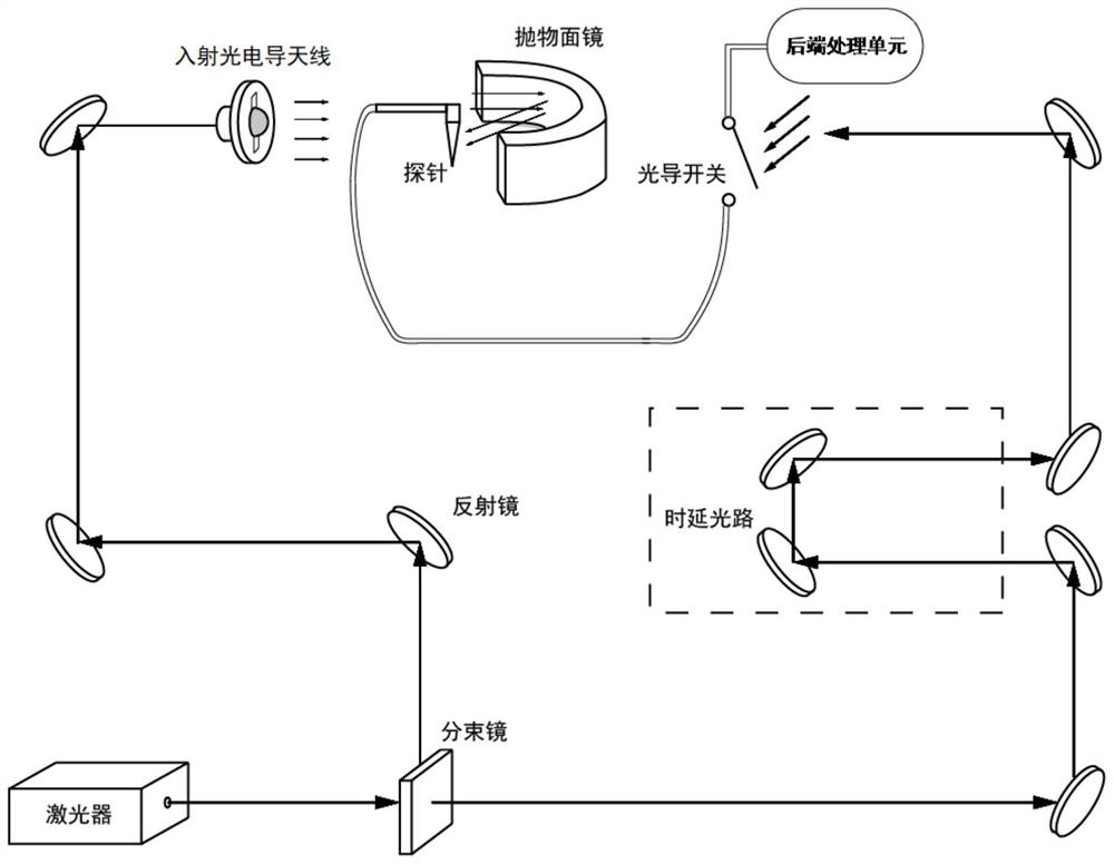
[0043] Such as figure 1 A terahertz near-field imaging system is shown, including a laser, an incident unit, a delay unit, a back-end processing unit, and a metal probe; where:

[0044] A laser is used to generate a femtosecond laser, the femtosecond laser is divided into incident light and detection light by a beam splitter, the incident light is transmitted to the incident unit, and the detection light is transmitted to the delay unit and then transmitted to the the photoconductive switch and trigger the photoconductive switch to conduct;

[0045] The incident unit includes an incident photoconductive antenna, a parabolic mirror and at least one reflective mirror, the incident photoconductive antenna is used to receive the incident light whose optical path is adjusted by the reflective mirror, and generate an incident signal incident to the parabolic mirror, and the parabolic mirror is used for Focusing the incident signal on the metal probe, the incident signal generates a...

Embodiment 2

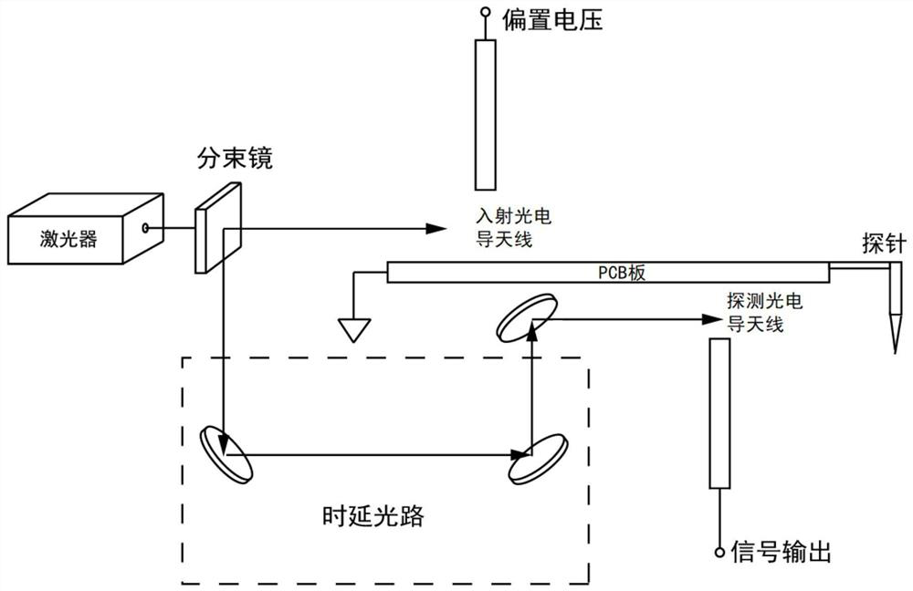
[0053] Such as figure 2 A terahertz near-field imaging system is shown, including a laser, an incident unit, a delay unit, a back-end processing unit, and a metal probe; where:

[0054] A laser is used to generate a femtosecond laser, the femtosecond laser is divided into incident light and detection light by a beam splitter, the incident light is transmitted to the incident unit, and the detection light is transmitted to the delay unit and then transmitted to the the photoconductive switch and trigger the photoconductive switch to conduct;

[0055] The incident unit includes an incident photoconductive antenna, the incident photoconductive antenna is connected to the metal probe through a transmission line, and the incident photoconductive antenna is used to generate an incident signal under the excitation of incident light, and the incident signal is conducted to the The metal probe generates a local field at the tip of the metal probe, and the local field is used to excit...

Embodiment 3

[0063] The terahertz near-field imaging method based on the imaging system in the above embodiment includes the following steps:

[0064] The femtosecond laser is divided into incident light and detection light by a spectroscope;

[0065] The incident light is converted into an incident signal. The incident signal excites the metal probe to generate a local field, and the local field excites the sample in the detection direction of the metal probe to generate a near-field signal. The near-field signal is coupled to a current signal on the metal probe and then passed through the metal probe. The probe and the transmission line are transmitted to the photoconductive switch;


PUM


Abstract

A terahertz near-field imaging system and method, the system includes a laser for generating femtosecond laser light, the femtosecond laser light is divided into incident light and detection light by a beam splitter, the incident light is transmitted to the incident unit, and the detection light is transmitted to the time-delay The unit is transmitted to the photoconductive switch after a delay and triggers the photoconductive switch to be turned on; the incident unit is used to generate an incident signal under the excitation of incident light, and the incident signal excites the metal probe to generate a local field, and the local field excites the metal probe to detect The sample in the direction generates a near-field signal; the metal probe is used to couple the near-field signal into a current signal, and the current signal is transmitted to the back-end processing unit through the metal probe, transmission line, and photoconductive switch; the back-end processing unit is used to receive and Process the current signal to obtain near-field information on the sample surface. The invention utilizes metal probes to excite and extract near-field signals on the sample surface in the form of electric current, which can not only significantly improve the signal-to-noise ratio and signal strength of near-field signals, but also greatly simplify the design of near-field optical paths.

Description

technical field [0001] The invention relates to the field of terahertz imaging, in particular to a terahertz near-field imaging system and method. Background technique [0002] Terahertz (THz) waves usually refer to electromagnetic waves with a frequency of 100 GHz to 10 THz and a wavelength of 30 to 3000 μm. Biological and semiconductor materials are prone to resonant optical properties. These characteristics make terahertz near-field imaging technology widely used in security inspection, chemical identification, medical imaging, quality control and other fields. In recent years, with the gradual maturity of technologies such as signal sources and detection methods in the terahertz frequency band, near-field high-resolution imaging technology in the terahertz frequency band has gradually developed. [0003] In the prior art, the scanning near-field optical microscope used in the terahertz frequency band is a scattering scanning near-field optical microscope, which mainly u...

Claims


Application Information

Patent Timeline
Patent Type & Authority Patents(China)
IPC IPC(8): G01Q60/18G01Q60/22
CPCG01Q60/18G01Q60/22
Inventor 胡旻王月莹
Owner 四川见微知著科技有限公司
Why Eureka
Try Eureka