
Anisotropic inner circle orientation multi-pole magnetic ring and mold and preparation method thereof

A multi-pole magnetic ring, anisotropic technology, used in the manufacture of inductors/transformers/magnets, permanent magnets, electrical components, etc., can solve the problem of low magnetic field in inner circle orientation, and achieve stable and quiet operation, good concentricity, Assemble simple effects

Inactive Publication Date: 2020-12-15
SINOSTEEL NANJING NEW MATERIALS RES INST CO LTD +1
View PDF10 Cites 8 Cited by
  • Summary
  • Abstract
  • Description
  • Claims
  • Application Information

AI Technical Summary

Problems solved by technology

[0009] Aiming at the problem that the inner circle orientation magnetic field of the existing anisotropic multi-pole magnetic ring is not high, the present invention provides an integral multi-pole magnetic ring, and provides an anisotropic inner circle orientation multi-pole magnetic ring mold, through Optimize the design of the mold so that the multi-pole magnetic ring is suitable for the electromagnetic orientation of the inner circle

Method used


Image

  • Anisotropic inner circle orientation multi-pole magnetic ring and mold and preparation method thereof
  • Anisotropic inner circle orientation multi-pole magnetic ring and mold and preparation method thereof
  • Anisotropic inner circle orientation multi-pole magnetic ring and mold and preparation method thereof

Examples


Embodiment 1

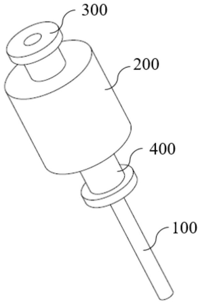
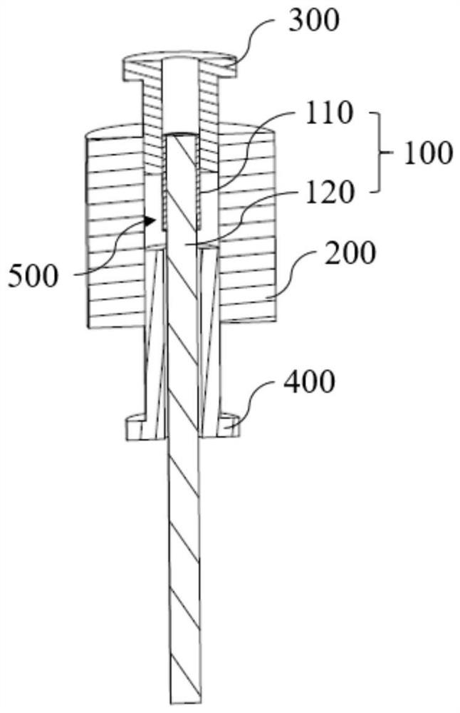
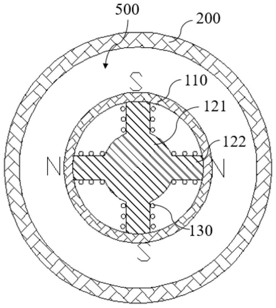
[0047] The mold for the anisotropic inner circle orientation multi-pole magnetic ring in this embodiment is an anisotropy for making D50*d30*H27-N4P (wherein: D means the outer diameter, d means the inner diameter, H means the height, and N means the inner circle orientation) A multi-pole magnetic ring filled with 4 poles, that is, the mold is provided with 4 protrusions 122, Figure 1-3 It is a schematic diagram of the mold structure of this embodiment.

[0048] The method for preparing the anisotropic inner circle oriented 4-pole magnetic ring of this embodiment using the above-mentioned mold is as follows:

[0049] (1) Powder making: The magnetic powder is made by uniformly mixing the primary formula and the secondary formula;

[0050] The primary formula is: 85 parts of iron oxide; 2.5 parts of calcium carbonate; 0.2 parts of silicon dioxide; 0.4 parts of boric acid; 1.2 parts of strontium carbonate, 5 parts of cobalt oxide, and 7 parts of lanthanum oxide;

[0051] The s...

Embodiment 2

[0058] The mold for the anisotropic inner circle orientation multi-pole magnetic ring in this embodiment is an anisotropy for making D37*d22*H15-N8P (where: D means the outer diameter, d means the inner diameter, H means the height, and N means the inner circle orientation) A multi-pole magnetic ring filled with 8 poles, that is, the mold is provided with 8 protrusions 122 .

[0059] Using the above-mentioned mold to prepare the anisotropic inner circle orientation 8-pole magnetic ring of this embodiment, the preparation method is as follows:

[0060] (1) Powder making: The magnetic powder is made by uniformly mixing the primary formula and the secondary formula;

[0061] The primary formula of magnetic powder is: 80 parts of iron oxide; 1 part of calcium carbonate; 0.1 part of silicon dioxide; 0.1 part of strontium carbonate; 0.2 part of polyvinyl chloride; 1 part of cobalt oxide and 3 parts of lanthanum oxide;

[0062] The secondary formula is: 0.2 part of calcium stearate;...

Embodiment 3

[0069] The mold of the anisotropic inner circle orientation multi-pole magnetic ring in this embodiment is an anisotropy for making D48*d40*H20-N6P (wherein: D means outer diameter, d means inner diameter, H means height, N means inner circle orientation) A multi-pole magnetic ring filled with 6 poles, that is, the mold is provided with 6 protrusions 122 .

[0070] The method for preparing the anisotropic inner circle oriented 4-pole magnetic ring of this embodiment using the above-mentioned mold is as follows:

[0071] (1) Powder making: The magnetic powder is made by uniformly mixing the primary formula and the secondary formula;

[0072] The primary formula of magnetic powder is: 90 parts of iron oxide; 5 parts of calcium carbonate; 1 part of silicon dioxide; 0.8 parts of boric acid; 2 parts of strontium carbonate; 1 part of polyvinyl chloride; 2.5 parts of cobalt oxide and 12 parts of lanthanum oxide;

[0073] The secondary formula is: 2 parts of calcium stearate; 1 part ...


PUM

PropertyMeasurementUnit
diameteraaaaaaaaaa
diameteraaaaaaaaaa
surface roughnessaaaaaaaaaa

Abstract

The invention discloses an anisotropic inner circle orientation multi-pole magnetic ring and a mold and a preparation method thereof, and belongs to the field of magnetic ring manufacturing. The multi-pole magnetic ring is an anisotropic 2n-pole magnetic ring with an oriented inner circle, n is a natural number, and the waveform of a magnetic circuit on the surface of the inner circle of the magnetic ring is a sinusoidal waveform; the mold comprises a core rod, an outer cylinder, an upper pressing head and a lower pressing head, and the core rod, the upper pressing head, the lower pressing head and the outer cylinder are matched and sleeved to form a mold cavity. The core rod comprises a sleeve and a magnet yoke, the magnet yoke comprises a base body and protruding parts, 2n protruding parts are distributed on the side face of the end, stretching into the upper pressing head, of the base body in the circumferential direction, copper wires are wound around the protruding parts respectively, and the protruding parts are sleeved with the sleeve in a matched mode. The preparation method comprises the following steps of: filling magnetic powder into the mold cavity, pressing the magnetic powder, electrifying a copper wire, applying a direct-current or pulsed magnetic field to the magnetic powder, orienting the magnetic powder, sintering, grinding and magnetizing to obtain the anisotropic inner circle orientation multi-pole magnetic ring. The multi-pole magnetic ring is directly manufactured into an integral stator magnetic ring, and stable and quiet operation of a motor is facilitated.

Description

technical field [0001] The invention belongs to the field of magnetic ring manufacturing, and more specifically relates to an anisotropic inner circle oriented multi-pole magnetic ring, a mold and a preparation method thereof. Background technique [0002] The magnetic device used as the stator in the motor generally exists in the form of magnetic tiles. Because of the magnetic leakage or the design requirements of the motor for the magnetic circuit, some occasions must require anisotropic multi-pole magnetic rings, which cannot be satisfied by the magnetic tiles. The magnetic tiles are used as the stator, which are generally even-numbered pieces (2 / 4 / 6 / 8 pieces, magnetized to the poles and pasted on the stator casing) to form a circular ring, which uses the magnetic field of its inner arc surface to provide energy. There is magnetic flux leakage in this method, because there is a phenomenon of poor concentricity in piece-by-piece assembly, and the waveform of the inner circ...

Claims


Application Information

Patent Timeline
Patent Type & Authority Applications(China)
IPC IPC(8): H01F7/02H01F41/02B22F3/03B22F5/10
CPCH01F7/02H01F41/0253H01F41/0266H01F41/0273B22F3/03B22F5/106
Inventor 张瑜裴晓东侯传河程朝华芦运
Owner SINOSTEEL NANJING NEW MATERIALS RES INST CO LTD
Learn More