Internal cooling device for PCB processing and processing method

A processing method and cooling medium technology, applied in electrical components, printed circuit manufacturing, printed circuits, etc., can solve the problems of blockage of internal cooling conveying channels, inability to circulate coolant, high temperature operation of drill bits, etc., to avoid tool wear and meet PCB requirements. Machining requirements, the effect of reducing cutting heat

Pending Publication Date: 2020-12-15
GUANGDONG UNIV OF TECH
View PDF0 Cites 0 Cited by
  • Summary
  • Abstract
  • Description
  • Claims
  • Application Information

AI Technical Summary

Problems solved by technology

During the mechanical processing of PCB, various problems caused by heat are prone to cause poor board quality. How to ensure the processing quality, avoid problems such as nail heads, residual glue, copper tumors, wicks, etc., and how to reduce tool wear and fracture and other issues have become the focus of processing
Although there is an internal cooling method to process workpieces in mechanical processing, due to the complexity of the PCB material and its high requirements for functional use, the internal cooling processing method of traditional mechanical processing is not suitable.
On the other hand, a large amount of chips will be generated during the drilling process, and these chips can easily enter the internal cooling delivery channel, resulting in blockage of the internal cooling delivery channel, making the coolant unable to circulate, resulting in cooling failure, high temperature operation of the drill bit, affecting the processing effect

Method used


Image

  • Internal cooling device for PCB processing and processing method
  • Internal cooling device for PCB processing and processing method
  • Internal cooling device for PCB processing and processing method

Examples


Embodiment Construction

[0032] In order to facilitate those skilled in the art to understand the present invention, the present invention will be further described in detail below in conjunction with specific embodiments and accompanying drawings.

[0033] The present application is further described in conjunction with the following examples.

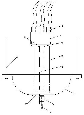
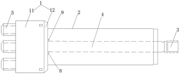
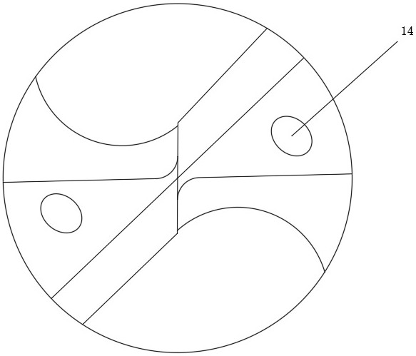
[0034] Such as Figure 1 to Figure 4 , an internal cooling device for PCB processing, including a pressure rotary joint 1, a main shaft 2 and a tool holder 3, the main shaft 2 is located between the tool holder 3 and the pressure rotary joint 1; the PCB processing The internal cooling device also includes an internal cooling delivery pipe 4 and a cooling medium multi-way interface 5 . Wherein, the internal cooling delivery pipe 4 is arranged in the pressure rotary joint 1, the main shaft 2 and the tool holder 3 and extends from the pressure rotary joint 1 tool holder 3 to the tool holder 3; the cooling medium multi-way interface 5 are arranged on the pressu...


PUM


Abstract

The invention relates to the technical field of PCB processing and particularly relates to an internal cooling device for PCB processing and a processing method. The internal cooling device for PCB processing comprises a pressure rotating joint, a main shaft, a cutter chuck, a cutter, an internal cooling conveying pipe and a cooling medium multi-way interface, wherein the main shaft is located between the cutter chuck and the pressure rotating joint; the inner cooling conveying pipe is arranged in the pressure rotary joint, the main shaft and the tool chuck, and the cooling medium multi-way connector is arranged on the pressure rotary joint and communicated with the inner cooling conveying pipe. According to the inner cooling device for PCB machining, the same or different cooling media can be directly conveyed to the position between a tool and a machined PCB through the cooling medium multi-way connector, heat generated in the machining process is reduced, the effect of reducing cutting heat is achieved through the most direct method, and the machining efficiency is improved; a problem that cutting heat generated between a cutter and a machined PCB is difficult to directly reducein other external cooling modes is solved, the cooling effect is optimal, and the influence of the cutting heat in PCB machining is greatly reduced.

Description

technical field [0001] The invention relates to the technical field of PCB processing, in particular to an internal cooling device for PCB processing and a processing method. Background technique [0002] Circuit boards, also known as printed circuit boards, also known as PCBs or printed circuit boards, are one of the important components of the electronics industry. Nowadays, aerospace, transportation, electronics, electrical machinery, medical, construction and other industrial products have been widely used by modern people. Under the demand of energy saving and light weight, more and more PCBs are used, including flexible boards, rigid boards, and rigid-flex boards. Due to the trend of thinner and multi-functional electronic products, domestic and foreign discussions on the development trend of PCB manufacturing technology in the future are basically consistent, that is, to high density, high precision, fine aperture, thin wire, fine pitch, high reliability, Multi-layer...

Claims


Application Information

Patent Timeline
Patent Type & Authority Applications(China)
IPC IPC(8): H05K3/00
CPCH05K3/0044H05K2203/0214H05K2203/1121
Inventor 郑李娟王成勇姚俊雄皮建鑫黄欣
Owner GUANGDONG UNIV OF TECH
Why Eureka
Try Eureka