Numerical-control roller bending device used for step guide rail bending, molding and processing

A technology of bending forming and bending device, applied in the field of machinery, can solve the problems of low material utilization rate and uncontrollable cross-sectional size, and achieve the effect of preventing sideslip

Pending Publication Date: 2020-12-25
JIANGSU TONGLI MACHINERY
View PDF0 Cites 3 Cited by
  • Summary
  • Abstract
  • Description
  • Claims
  • Application Information

AI Technical Summary

Problems solved by technology

The traditional process of ladder guide rail is completed by stretch bending. Although the process is simple, the cross-sectional size of the stretch bend cannot be controlled after stretching, and the material utilization rate is extremely low.

Method used


Image

  • Numerical-control roller bending device used for step guide rail bending, molding and processing
  • Numerical-control roller bending device used for step guide rail bending, molding and processing
  • Numerical-control roller bending device used for step guide rail bending, molding and processing

Examples


Embodiment 1

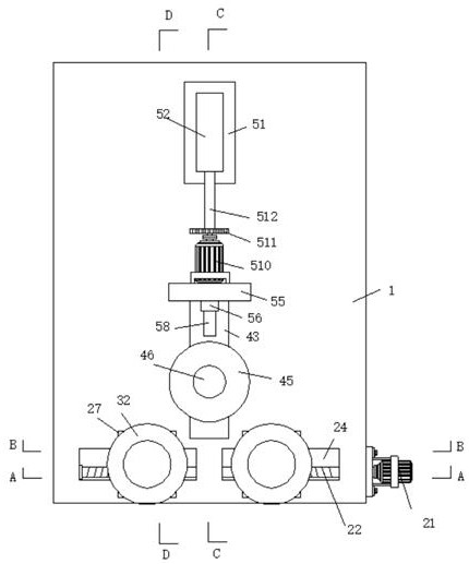
[0049]Assemble the required fixed mold 32 and movable mold 45, turn on the external power supply, place the ladder rails that need to be rolled in the grooves of the two fixed molds 32, start the hydraulic cylinder 52, and the hydraulic cylinder 52 pushes the hydraulic rod 512 to move , The hydraulic rod 512 pushes the vertical plate 55 to move, and the vertical plate 55 drives the vertical rod 54 and the limit slider 53 at the lower end to slide along the long groove 41 and the bottom groove 43, respectively, and the limit slider 53 and the bottom groove 43 can maintain the vertical The plate 55 slides steadily without tilting. The vertical plate 55 pushes the load-bearing screw 58 to run through the threads in the threaded long groove 57. The reinforcement block 56 increases the number of threads to make the thrust more stable. The load-bearing screw 58 pushes the mold 45 to move. The mold 45 drives the slide bar 42 and the bottom plate 44 to slide in the long groove 41 and the bo...

Embodiment 2

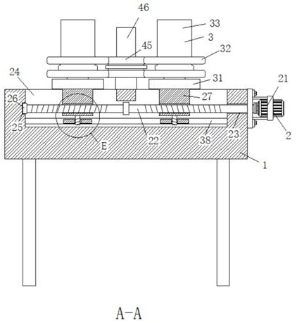
[0051]If the bending amplitude of the stairway guide rail needs to be increased in length, the first motor 21 is controlled to start, and the first motor 21 drives the two-way threaded rod 22 to rotate. The two ends of the two-way threaded rod 22 are in opposite directions, and the two slides are driven by the opposite threads. The block 27 slides to both ends. The first motor 21 adopts a servo motor. Through the control system, the number of turns and the angle of rotation are precisely controlled, and the two-way threaded rod 22 is driven to rotate by a fixed number of turns. The distance between the two sliders 27 can be precisely controlled. The distance between them is such that when rolling with the ladder rail parts, the supporting point of the bending force becomes larger, and the bending amplitude is correspondingly increased. The first motor 21 is controlled by the numerical control system to achieve precise adjustment. If the bending amplitude needs to be reduced, the fir...

Embodiment 3

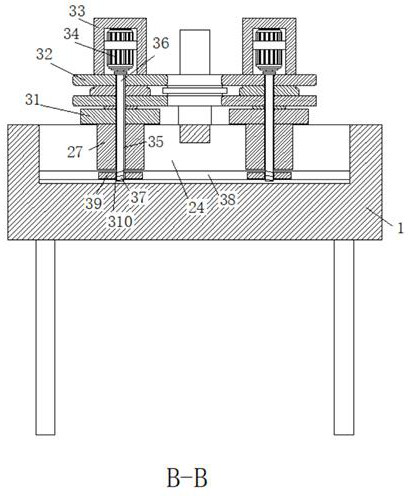
[0053]When rolling, the movable die 45 squeezes the ladder rail onto the fixed die 32. During the continuous extrusion, the ladder rail is bent, and the contact point between the curved ladder rail and the two fixed die 32 changes. , Resulting in a slight change in the force direction of the fixed mold 32, the two fixed molds 32 as backers, may slide along the direction of the chute 24 when bearing the roller pressure, start the second motor 34, the second motor 34 drives the rotating rod 36 rotates, the external thread 37 at the bottom of the rotating rod 36 drives the sliding plate 39 upward under the action of the threaded hole 310. The sliding plate 39 cannot move up in the limiting groove 38, so it tightly abuts on the upper surface of the limiting groove 38. The entire fixed mold mechanism 3 is fixed, and friction is generated during rolling to prevent side slip. Since the lateral extrusion force angle of the ladder rail against the fixed mold 32 is small, the force component ...


PUM


Abstract

The invention discloses a numerical-control roller bending device used for step guide rail bending, molding and processing. The numerical-control roller bending device used for step guide rail bendingcomprises a main body, wherein a spacing regulating mechanism is arranged inside the main body; two fixed mold mechanisms are arranged at the upper end of the spacing regulating mechanism; a movablemold mechanism is arranged on the upper surface of the main body; and one end of the upper surface of the main body is equipped with a pressure mechanism. The numerical-control roller bending device disclosed by the invention has the beneficial effects that: spacing regulation between the two fixed mold mechanisms is more synchronous by the spacing regulating mechanism via a two-way threaded rod,and manual operation is not needed; step guide rails of different bending amplitudes are rolled by regulating different spacings, and contact points between fixed molds of the two fixed mold mechanisms and the step guide rails change, so that a slide block can be effectively fixed through a slide plate and a limiting slot without sliding; and a third motor is used for regulating, so that a strokeof a hydraulic rod can be changed to change movement amount of the movable molds to change depth of roller-pressing, and thus, roller-pressing radian of the step guide rails can be freely regulated.

Description

Technical field[0001]The invention relates to a guide rail bending device, in particular to a numerical control roller bending device used for bending and forming of ladder road guide rails, and belongs to the technical field of machinery.Background technique[0002]The escalator is a combination of a chain conveyor with a special structure and two belt conveyors with a special structure, with a circular movement ladder to move up or down between different floors of the building Stationary electric drive equipment for inclined transportation of passengers. A continuous conveying machine that carries people up and down.[0003]In recent years, with the continuous increase of urbanization, the rapid development of urban transportation, urban transportation construction, and a large number of subway transportation projects have greatly promoted the escalator industry. The traditional process of stairway guide rails is completed by drawing and bending. Although the process is simple, the cr...

Claims


Application Information

Patent Timeline
Patent Type & Authority Applications(China)
IPC IPC(8): B21D7/08
CPCB21D7/08
Inventor 李国平
Owner JIANGSU TONGLI MACHINERY
Why Eureka
Try Eureka