Automatic tissue specimen sampling equipment

A tissue specimen, automatic sampling technology, applied in the direction of cap, liquid handling, liquid distribution, conveying or transfer device, etc., can solve problems such as low efficiency, and achieve the effect of high degree of automation and high packaging efficiency

Active Publication Date: 2020-12-25
宁波之凌智能科技有限责任公司
View PDF7 Cites 6 Cited by
  • Summary
  • Abstract
  • Description
  • Claims
  • Application Information

AI Technical Summary

Problems solved by technology

The current process of collecting tissue samples, filling liquid and encaps...

Method used


Image

  • Automatic tissue specimen sampling equipment
  • Automatic tissue specimen sampling equipment
  • Automatic tissue specimen sampling equipment

Examples


Embodiment 1

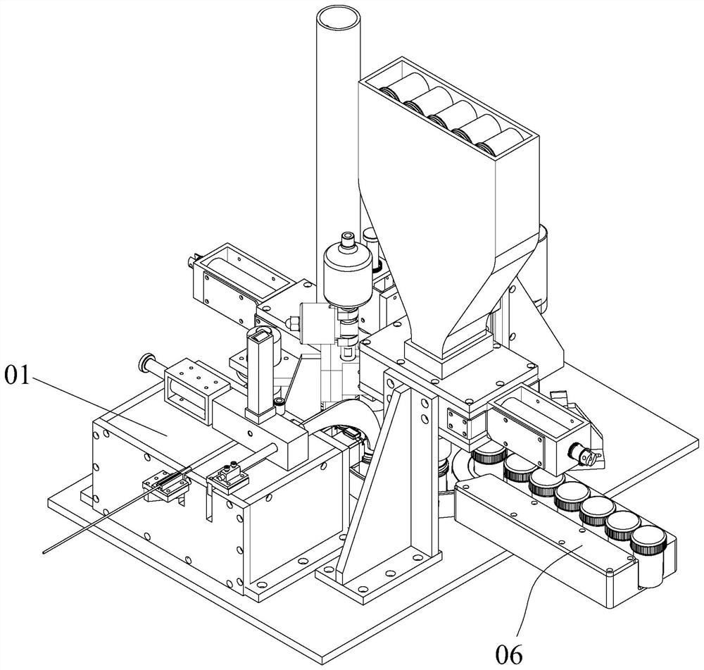
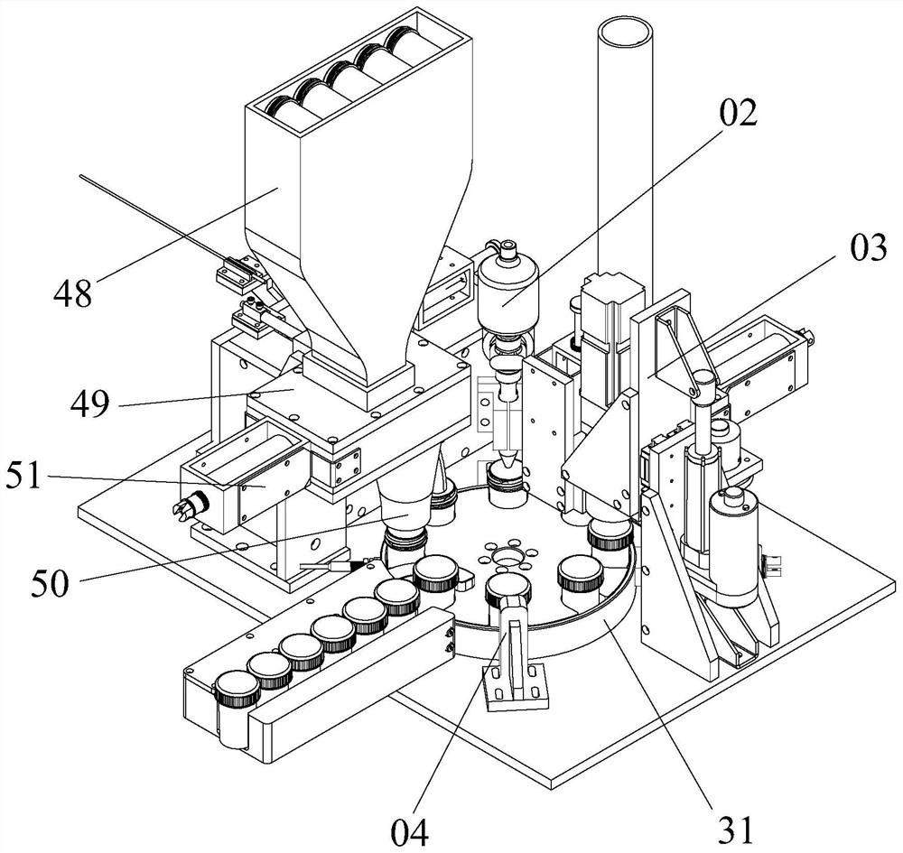
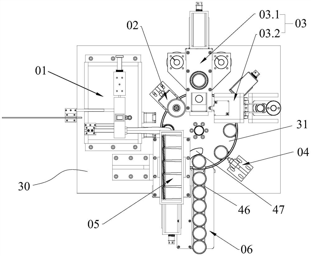
[0055] Such as figure 1 , 2 , 3, the present invention provides a tissue sample automatic sampling device, including a bottom plate 30, on which a collecting mechanism 01, a liquid filling structure 02 and a capping mechanism 03 are sequentially arranged, and a transmission mechanism is also arranged on the bottom plate 30 , which is used to drive the specimen collection container through the stations where the collection mechanism 01, liquid filling structure 02 and capping mechanism 03 are located in order to realize the automatic collection of tissue specimens, automatic liquid filling, automatic capping and other processes, replacing the prior art The manual collection of tissue samples, manual liquid filling, manual capping and other operations are faster and more efficient.

[0056] In this structure, the collection mechanism 01, the liquid filling structure 02 and the capping mechanism 03 can be arranged along the same straight line, that is, a linear assembly line is ...

Embodiment 2

[0091] Such as Figure 11 As shown, the structure of this implementation is basically the same as that of Embodiment 1, and the only difference is the specific structural form of the separation component. The separation component in the first embodiment relies on the adsorption of the vacuum equipment to absorb and adhere the tissue specimen on the biopsy forceps 110 to the sample tube 100. Since there are relatively few vacuum equipment in actual production, another method is adopted in this embodiment. A separate form, as follows:

[0092] In this embodiment, the separation mechanism includes an air pipe 12 and an air blowing device 60. The air blowing device 60 is arranged on the installation block 6 at a position corresponding to the first station, specifically the position corresponding to the first through hole 6.2. The air device 60 is provided with a joint 60.1 connected with an external air pump. One end of the air pipe 12 is connected to the other end of the mounti...

Embodiment 3

[0094] The structure of this embodiment is the same as that of Embodiment 1, the only difference is that the specific structures of the positioning component and the separation component are different; specifically, as Figure 12 , 13 As shown, the positioning component in this embodiment includes:

[0095] The mounting frame 10 is provided with a positioning plate 11 for rotation on the mounting frame 10, and at least one accommodating groove 14 for accommodating the sample tube 100 is provided on the outer wall of the positioning plate 11, and the second driving mechanism drives the positioning plate 11 to rotate so that The sample tube 100 in the holding tank 14 is switched between the first station and the second station. In this embodiment, the second driving mechanism is a rotary stepping motor, and the output shaft of the rotary stepping motor is connected to the positioning disc 11, and the positioning disc 11 is driven to rotate in a circumferential direction by the ...


PUM


Abstract

The invention discloses automatic tissue specimen sampling equipment which comprises a bottom plate. A collecting mechanism, a liquid filling mechanism, a capping mechanism and a conveying mechanism are sequentially arranged on the bottom plate; the collecting mechanism is used for collecting tissue specimens on biopsy forceps into specimen bottles; the liquid filling mechanism is used for automatically filling quantitative preservative liquid into the specimen bottles; the capping mechanism is used for automatically capping bottle caps at the open ends of the specimen bottles; and the conveying mechanism is used for sequentially conveying the specimen bottles to corresponding stations of the collecting mechanism, the liquid filling mechanism and the capping mechanism, so that automatic collection, liquid filling and packaging of the tissue specimens are realized. The automatic tissue specimen sampling equipment disclosed by the invention is simple in structure, the processes of separation, collection, filling, capping and the like of the tissue specimens are integrated and automatically completed, and manual operation is not needed in the period, so that the automation degree is high, and the packaging efficiency is high.

Description

technical field [0001] The invention relates to the technical field of living body sampling, in particular to an automatic sampling device for tissue samples. Background technique [0002] With the development of modern science and technology, the endoscope has been completely reformed and uses optical fibers. In 1964, Japan successfully developed a biopsy forceps device for fiberoptic endoscopes. This kind of biopsy forceps can obtain suitable pathological materials and is less dangerous. Endoscopy in the modern sense is gradually formed with the realization of fiber optic endoscope. In November 2002, the world's first "high-definition endoscopy system" was born, and the concept of endoscopy has undergone great changes. It integrates cutting-edge imaging technology, and the image accuracy provided makes it possible to diagnose extremely small lesions. [0003] However, the current biopsy device needs to manually peel off the tissue sample from the biopsy forceps and put ...

Claims


Application Information

Patent Timeline
IPC IPC(8): B65G43/08B65G47/42B65G47/88B67B3/20B67D7/02B41J3/36B41J3/407B41J3/44
CPCB65G43/08B65G47/42B65G47/8807B67D7/02B67B3/2066B67B3/20B41J3/4073B41J3/36B41J3/44A61B10/06A61B10/0096G01N35/025
Inventor 金之凌
Owner 宁波之凌智能科技有限责任公司
Why Eureka
Try Eureka