
Cement kiln head waste heat boiler and cement line grate cooler integrated device

A waste heat boiler and grate cooler technology, applied in furnaces, waste heat treatment, furnace components, etc., can solve problems such as increased power consumption of cement lines, loss of power generation, increased power consumption of cement line exhaust fans, etc., to improve energy utilization efficiency, solve the wear problem, and improve the effect of power generation efficiency

Pending Publication Date: 2020-12-25
SINOMA ENERGY CONSERVATION
View PDF0 Cites 0 Cited by
  • Summary
  • Abstract
  • Description
  • Claims
  • Application Information

AI Technical Summary

Problems solved by technology

[0003] However, in the traditional layout, not only the front dust separation device and the waste heat boiler need to occupy the factory space, but also the waste heat boiler device needs to be rooted from the ground as the foundation, and the distance of the smoke and air pipeline is long, which brings a large amount of civil engineering and non-standard engineering. Increased project construction investment cost. At the same time, the temperature loss and pressure loss are relatively large. After calculation, the temperature loss from the air inlet of the grate cooler to the air inlet of the waste heat boiler is about 20-30℃, and the pressure loss is about 300-500Pa. The loss of power generation reached 1.5kWh / t.cl. At the same time, the increase in system resistance brought about an increase in the power consumption of the cement line exhaust fan, which increased by about 0.2kWh / t.cl. The loss of power generation also increased the power consumption of the cement line

Method used


Image

  • Cement kiln head waste heat boiler and cement line grate cooler integrated device
  • Cement kiln head waste heat boiler and cement line grate cooler integrated device
  • Cement kiln head waste heat boiler and cement line grate cooler integrated device

Examples


Embodiment Construction

[0017]The present invention will be further described below according to specific embodiments.

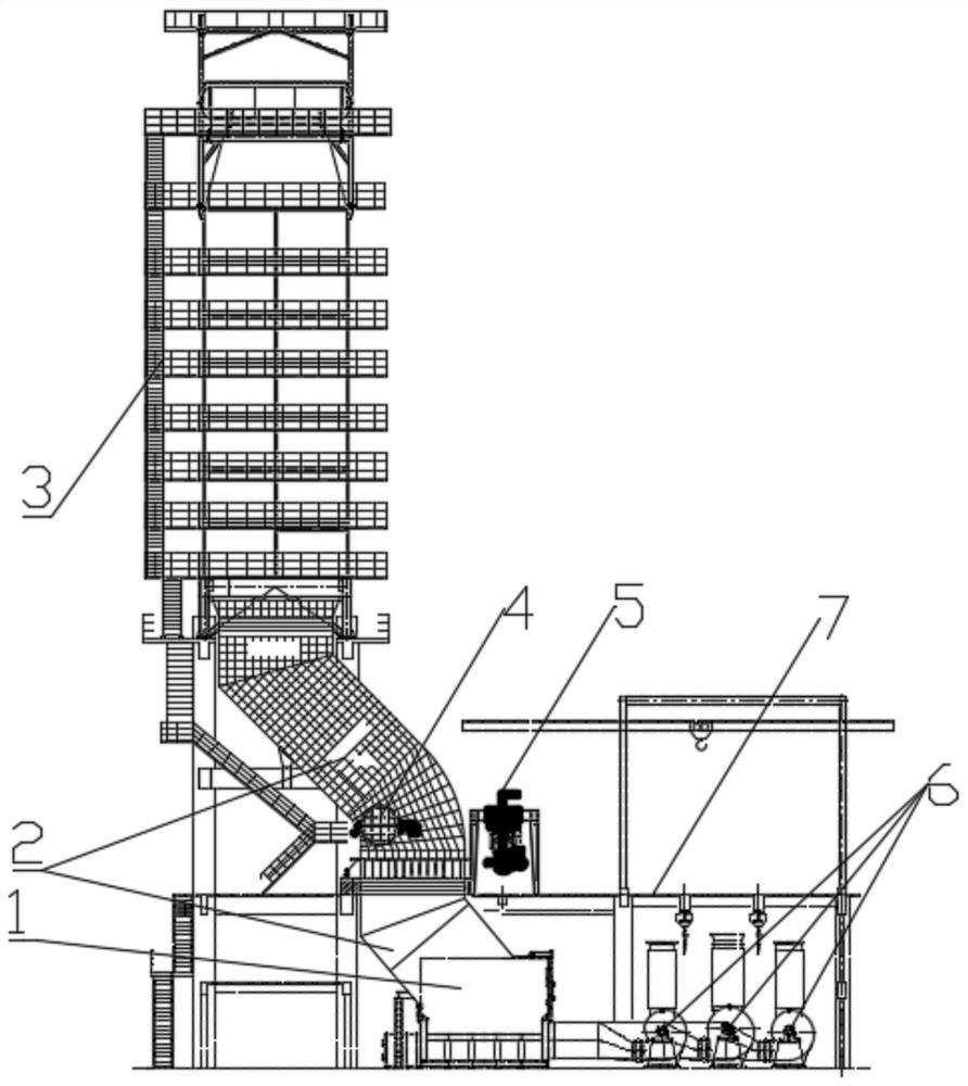
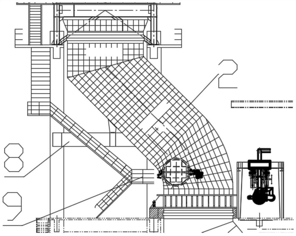
[0018]Such asFigure 2-3The shown integrated device of cement kiln head waste heat boiler and cement line grate cooler includes a base frame and an AQC boiler 3 fixedly installed on the base frame. The AQC boiler 3 adopts a vertical arrangement, and the upper end of the AQC boiler 3 is provided with a dust collector The bottom of the AQC boiler 3 is connected with a flue 2, and the cross-sectional shape of the flue 2 is rectangular. The flue 2 is vertically inclined and penetrates the cement line kiln head operating layer platform 7. A grate cooler 1 is installed under the cement line kiln head operating layer platform 7. The exhaust gas outlet of the grate cooler 1 is connected with the flue inlet, and the grate cooler The air inlet of the machine 1 is connected with the air supply pipe. The air supply pipe is equipped with a fan 6, and the flue 2 is also equipped with a mixed cooling air v...


PUM


Abstract

The invention provides a cement kiln head waste heat boiler and cement line grate cooler integrated device. The cement kiln head waste heat boiler and cement line grate cooler integrated device comprises a base frame and an AQC boiler fixedly installed on the base frame, wherein the bottom of the AQC boiler is connected with a flue, the flue is longitudinally and obliquely arranged and runs through a cement line kiln head operation layer platform, a grate cooler is arranged below the cement line kiln head operation layer platform, a tail gas outlet of the grate cooler is connected with one airinlet of the flue, one air inlet of the grate cooler is connected with an air supply pipeline, air fans are arranged in the air supply pipeline, a cold air mixing valve is further arranged on the flue and is located above the cement line kiln head operation layer platform, and a coal injection combustor is arranged on the cement line kiln head operation layer platform. By means of the cement kilnhead waste heat boiler and cement line grate cooler integrated device, the power generation efficiency is greatly improved, the cement line power consumption is saved, and the energy utilization rateis increased.

Description

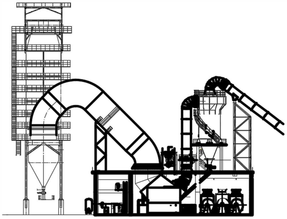
Technical field[0001]The invention relates to the technical field of cement kiln waste heat power generation, and more specifically, to an integrated device of cement kiln head waste heat boiler and cement line grate cooler.Background technique[0002]Cement kiln head waste heat boiler is an equipment that uses waste heat from cement line grate coolers to generate low-pressure superheated steam for power generation. More importantly, it is also the cement line's cooling and temperature reduction equipment. After cooling, it meets the inlet air temperature requirements of the dust collector. Currently, the conventional way isfigure 1 As shown, the kiln head waste heat boiler is arranged on the open space next to the kiln head grate cooler plant, and the grate cooler and the waste heat boiler are connected by a long-distance flue gas duct. After the flue gas passes through the front dust separation device, Then it enters the waste heat boiler, enters the dust collector after heat exchan...

Claims


Application Information

Patent Timeline
Patent Type & Authority Applications(China)
IPC IPC(8): F27D17/00F27D15/02
CPCF27D15/022F27D17/004Y02P10/25
Inventor 董兰起曲贺邹军辉张迎春李勇杨镇曹伟张国平李大庆陶军普
Owner SINOMA ENERGY CONSERVATION
Learn More