


Quick Research
Generate reliable direction feasibility study reports for your R&D in just a few steps.

Technical Q&A
Discover and master advanced knowledge NOW. Basics, ideas, possibilities, all at once.

Find Solutions
As an expert in R&D theories, this can generate solutions to your technical problems instantly.

Evaluate Feasibility
Analyze your overall solution with one click, know your potential R&D risks in advance.

Monitor Landscape
Get weekly tech updates, stay abreast of the latest tech innovations and key insights.
Back polishing method of PERC battery
A back-polishing and back-polishing technology, applied in the field of solar cells, can solve the problems of increasing oxidation processes, back surface defects, and inability to take both into account, so as to achieve the effects of improving light reflectivity, improving flatness, and solving loss and composite loss.
- Summary
- Abstract
- Description
- Claims
- Application Information
AI Technical Summary
Problems solved by technology
Method used
Image

Examples
Embodiment 1
[0083] The back polishing method of the PERC cell of the present embodiment comprises the following steps:
[0084] S11, removing the organic matter on the surface of the silicon wafer and the damaged layer during the cutting process of the silicon wafer;
[0085] S12. Phosphorus is diffused on the surface of the silicon wafer using a phosphorus oxychloride liquid source to form a PN junction on the surface of the silicon wafer; during the diffusion process, the surface of the silicon wafer will be covered with a phosphosilicate glass layer;
[0086] S13. Using a laser to locally irradiate the phosphosilicate glass layer on the surface of the silicon wafer according to the metallization pattern, so as to form a local re-diffusion area on the surface of the silicon wafer.
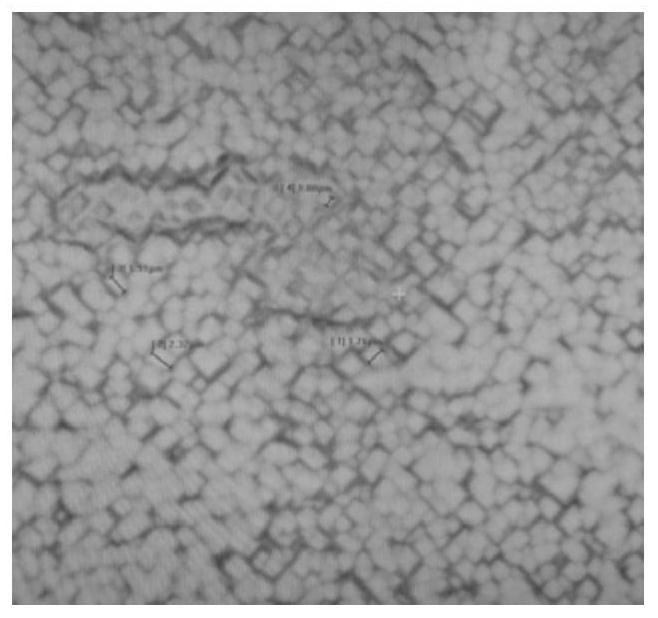
[0087] S2, place the silicon wafer in HF, H 2 SO 4 、HNO 3 with H 2 The volume ratio of O is 1:0.3:2.6:1 for back polishing in a mixed solution to form a textured surface with a square or rectangular stru...
Embodiment 2
[0096] The back polishing method of the PERC cell of the present embodiment comprises the following steps:
[0097] S11, removing the organic matter on the surface of the silicon wafer and the damaged layer during the cutting process of the silicon wafer;
[0098] S12. Phosphorus is diffused on the surface of the silicon wafer using a phosphorus oxychloride liquid source to form a PN junction on the surface of the silicon wafer; during the diffusion process, the surface of the silicon wafer will be covered with a phosphosilicate glass layer;
[0099] S13. Using a laser to locally irradiate the phosphosilicate glass layer on the surface of the silicon wafer according to the metallization pattern, so as to form a local re-diffusion area on the surface of the silicon wafer.
[0100] S2, place the silicon wafer in HF, H 2 SO 4 、HNO 3 with H 2 The volume ratio of O is 1:1.5:3.0:1.8 for back polishing in a mixed solution to form a textured surface with a similar square or rectan...
Embodiment 3
[0109] The back polishing method of the PERC cell of the present embodiment comprises the following steps:
[0110] S11, removing the organic matter on the surface of the silicon wafer and the damaged layer during the cutting process of the silicon wafer;
[0111] S12. Phosphorus is diffused on the surface of the silicon wafer using a phosphorus oxychloride liquid source to form a PN junction on the surface of the silicon wafer; during the diffusion process, the surface of the silicon wafer will be covered with a phosphosilicate glass layer;
[0112] S13. Using a laser to locally irradiate the phosphosilicate glass layer on the surface of the silicon wafer according to the metallization pattern, so as to form a local re-diffusion area on the surface of the silicon wafer.
[0113] S2, place the silicon wafer in HF, H 2 SO 4 、HNO 3 with H 2 The volume ratio of O is 1:1:2.8:1.5 for back polishing in a mixed solution to form a textured surface with a similar square or rectangu...
PUM
 Abstract
Description
Claims
Application Information
 - R&D Engineer
- R&D Manager
- IP Professional
- Industry Leading Data Capabilities
- Powerful AI technology
- Patent DNA Extraction
Browse by: Latest US Patents, China's latest patents, Technical Efficacy Thesaurus, Application Domain, Technology Topic, Popular Technical Reports.
© 2024 PatSnap. All rights reserved.Legal|Privacy policy|Modern Slavery Act Transparency Statement|Sitemap|About US| Contact US: help@patsnap.com