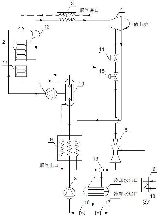
Waste heat recovery and power cooling combined supply system for ship gas turbine
A gas turbine and waste heat recovery technology, applied to heat exchangers, mechanical equipment, indirect heat exchangers, etc., to achieve the effects of improving overall efficiency, improving comfort, and reducing irreversible losses
- Summary
- Abstract
- Description
- Claims
- Application Information
AI Technical Summary
Problems solved by technology
Method used
Image
Examples
Embodiment 1
[0022] Such as figure 1As shown, the ship gas turbine waste heat recovery system includes ORC liquid supply pump 1, ORC steam generator 2, ORC superheater 3, ORC turbine 4, ejector 5, refrigeration evaporator 6, and condenser 7. Low-pressure liquid supply pump 8, low-pressure preheater 9, low-pressure steam generator 10, low-pressure superheater 11, steam drum 12, mixer 13, regulating valve, stop valve and throttle valve 18; ship gas turbine flue gas in sequence After passing through the ORC superheater 3, ORC steam generator 2, low-pressure superheater 11, low-pressure steam generator 10 and low-pressure preheater 9, the heat is released from the flue gas outlet of the low-pressure preheater 9; the steam at the top of the low-pressure steam generator 10 The outlet of the working medium is connected to the inlet of the low-pressure superheater 11, and the outlet of the superheated steam working medium of the low-pressure superheater 11 is divided into two routes, one of which ...
Embodiment 2
[0025] Such as figure 1 As shown, the ship gas turbine waste heat recovery system includes ORC liquid supply pump 1, ORC steam generator 2, ORC superheater 3, ORC turbine 4, ejector 5, refrigeration evaporator 6, and condenser 7. Low-pressure liquid supply pump 8, low-pressure preheater 9, low-pressure steam generator 10, low-pressure superheater 11, steam drum 12, mixer 13, regulating valve, stop valve and throttle valve 18; ship gas turbine flue gas in sequence After passing through the ORC superheater 3, ORC steam generator 2, low-pressure superheater 11, low-pressure steam generator 10 and low-pressure preheater 9, the heat is released from the flue gas outlet of the low-pressure preheater 9; the steam at the top of the low-pressure steam generator 10 The outlet of the working medium is connected to the inlet of the low-pressure superheater 11, and the outlet of the superheated steam working medium of the low-pressure superheater 11 is divided into two routes, one of which...
Embodiment 3
[0028] Such as figure 1 As shown, the ship gas turbine waste heat recovery system includes ORC liquid supply pump 1, ORC steam generator 2, ORC superheater 3, ORC turbine 4, ejector 5, refrigeration evaporator 6, and condenser 7. Low-pressure liquid supply pump 8, low-pressure preheater 9, low-pressure steam generator 10, low-pressure superheater 11, steam drum 12, mixer 13, regulating valve, stop valve and throttle valve 18; ship gas turbine flue gas in sequence After passing through the ORC superheater 3, ORC steam generator 2, low-pressure superheater 11, low-pressure steam generator 10 and low-pressure preheater 9, the heat is released from the flue gas outlet of the low-pressure preheater 9; the steam at the top of the low-pressure steam generator 10 The outlet of the working medium is connected to the inlet of the low-pressure superheater 11, and the outlet of the superheated steam working medium of the low-pressure superheater 11 is divided into two routes, one of which...
PUM
 Abstract
Description
Claims
Application Information
 - R&D
- Intellectual Property
- Life Sciences
- Materials
- Tech Scout
- Unparalleled Data Quality
- Higher Quality Content
- 60% Fewer Hallucinations
Browse by: Latest US Patents, China's latest patents, Technical Efficacy Thesaurus, Application Domain, Technology Topic, Popular Technical Reports.
© 2025 PatSnap. All rights reserved.Legal|Privacy policy|Modern Slavery Act Transparency Statement|Sitemap|About US| Contact US: help@patsnap.com

