Graphite tank for sintering silicon carbide ceramic tube, high-performance silicon carbide ceramic tube and preparation method thereof

A silicon carbide ceramic and graphite groove technology, applied in the field of engineering ceramic materials, can solve problems such as difficulty in ensuring the straightness and roundness of pipes

Active Publication Date: 2021-07-13
SHANGHAI INST OF CERAMIC CHEM & TECH CHINESE ACAD OF SCI
View PDF7 Cites 0 Cited by
  • Summary
  • Abstract
  • Description
  • Claims
  • Application Information

AI Technical Summary

Problems solved by technology
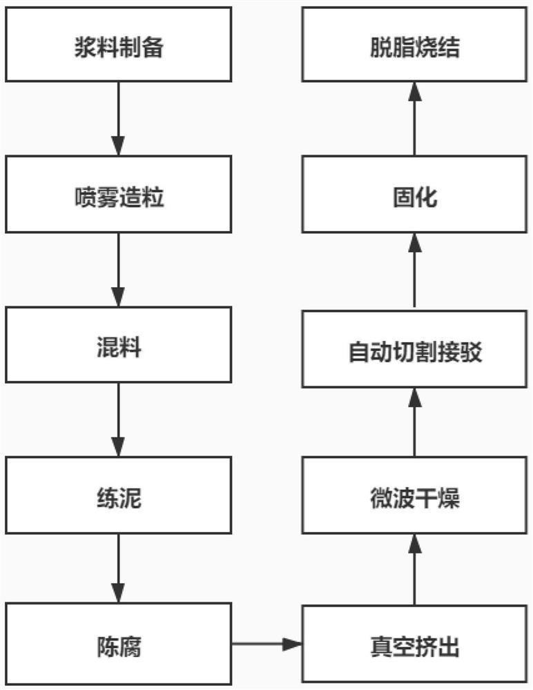
Therefore, the existing graphite groove is also difficult to ensure the straightness and roundness of the tube after sintering

Method used


Image

  • Graphite tank for sintering silicon carbide ceramic tube, high-performance silicon carbide ceramic tube and preparation method thereof
  • Graphite tank for sintering silicon carbide ceramic tube, high-performance silicon carbide ceramic tube and preparation method thereof
  • Graphite tank for sintering silicon carbide ceramic tube, high-performance silicon carbide ceramic tube and preparation method thereof

Examples


Embodiment 1

[0076] 1) Slurry preparation:

[0077] The main raw material is composed of the following components by weight: 99.5wt% submicron silicon carbide powder and 0.5wt% boron carbide;

[0078] Add 1.0wt% polyethylene glycol, 0.3wt% tetramethylammonium hydroxide, and 10.0wt% water-based phenolic resin into deionized water, and stir for 5 minutes to dissolve and disperse evenly to form an aqueous solution of organic additives. The total weight of deionized water is 125wt% of the silicon carbide powder;

[0079] The organic additive aqueous solution, submicron silicon carbide powder, and boron carbide are sequentially added into a sand mill, and there are 200wt% silicon carbide ceramic balls in the sand mill, and stirred evenly to form a silicon carbide slurry. Slurry ball milling time is 4h;

[0080] 2) Spray granulation:

[0081] The above slurry is subjected to spray granulation, wherein the inlet temperature is 220°C and the outlet temperature is 110°C;

[0082] 3) Mixing:

...

Embodiment 2

[0098] 1) Slurry preparation:

[0099] The main raw material is composed of the following components by weight: 99.7wt% submicron silicon carbide powder and 0.3wt% boron carbide;

[0100] Add 0.5wt% polyethylene glycol, 0.5wt% tetramethylammonium hydroxide, and 12.0wt% water-based phenolic resin into deionized water, and stir for 8 minutes to dissolve and disperse evenly to form an aqueous solution of organic additives. The total weight of deionized water is 110wt% of the silicon carbide powder;

[0101] The organic additive aqueous solution, submicron silicon carbide powder, and boron carbide are sequentially added into a sand mill, which contains 150 wt% silicon carbide ceramic balls, and stirred evenly to form a silicon carbide slurry. The slurry ball milling time is 2h.

[0102] 2) Spray granulation:

[0103] The above slurry is subjected to spray granulation, wherein the inlet temperature is 210°C and the outlet temperature is 100°C;

[0104] 3) Mixing:

[0105] The ...

Embodiment 3

[0119] After the obtained spray granulation powder is directly added into deionized water, it is smelted and stale. The rest are identical to Example 2.


PUM

PropertyMeasurementUnit
lengthaaaaaaaaaa
lengthaaaaaaaaaa
particle diameteraaaaaaaaaa

Abstract

The invention relates to a graphite groove for sintering a silicon carbide ceramic tube, a high-performance silicon carbide ceramic tube and a preparation method thereof. The graphite groove is a V-shaped graphite groove with an arc top angle, wherein: the arc top angle is a circular arc The diameter of the part = the outer diameter of the required silicon carbide ceramic tube + (0.1 ~ 0.3) mm, the angle of the V-shaped graphite groove α = 2 × arcsin (m / M)-x, where 0≤x≤2, where m is The silicon carbide ceramic tube blank is placed on a flat graphite plate for degreasing and sintering, and the outer diameter roundness of the obtained silicon carbide ceramic tube can be maintained at ±0.1mm. The corresponding maximum unit length mass of the silicon carbide ceramic tube blank; M is the mass per unit length of the silicon carbide ceramic tube blank to be degreased and sintered, m<M≤8.0g / cm. The graphite groove can make the silicon carbide ceramic tube fit into the top angle of the arc to the greatest extent at the end of the sintering shrinkage process, which improves the straightness, roundness and strength of the ceramic tube.

Description

technical field [0001] The invention relates to a graphite tank for sintering silicon carbide ceramic tubes, a high-performance silicon carbide ceramic tube and a preparation method thereof, belonging to the technical field of engineering ceramic materials. Background technique [0002] With the development of the national economy, the society has put forward higher requirements for energy efficiency and energy conservation management of key industrial energy-consuming equipment. As a thermal energy conversion device commonly used in industry, the heat exchanger's energy efficiency level directly affects the energy saving of the industrial industry. Therefore, thermal conductivity, reliable operation and stability, and surface cleanliness of heat exchange components have become important indicators to measure the quality of heat exchange components in heat exchangers. [0003] At present, shell and tube heat exchangers are the most widely used industrial heat exchangers, an...

Claims


Application Information

Patent Timeline
Patent Type & Authority Patents(China)
IPC IPC(8): F27D5/00C04B35/565C04B35/622
CPCC04B35/565C04B35/622C04B2235/3821C04B2235/5445C04B2235/6021C04B2235/606C04B2235/656C04B2235/6567C04B2235/77C04B2235/94C04B2235/95C04B2235/96F27D5/0068
Inventor 黄政仁张玉强刘学建陈忠明杨金晶裴兵兵姚秀敏
Owner SHANGHAI INST OF CERAMIC CHEM & TECH CHINESE ACAD OF SCI
Why Eureka
Try Eureka