
Universal high-temperature heat pipe type heat absorber

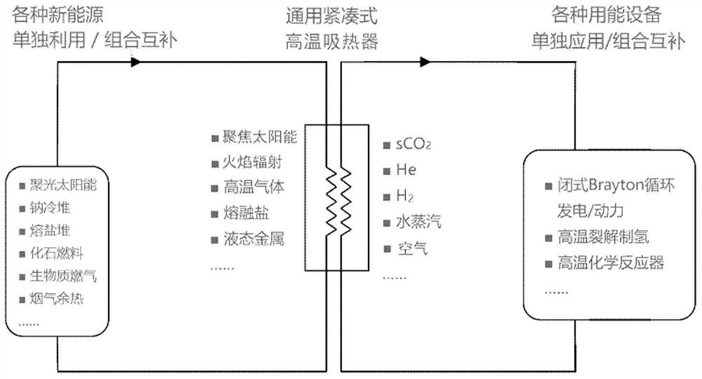
A heat absorber and heat pipe type technology, applied in the field of general-purpose high-temperature heat pipe heat absorbers, can solve the problems of inconvenient complementary and comprehensive utilization of multiple heat sources, uneven temperature distribution, limited space layout, etc., and achieve universality , large heat transfer and low flow rate of working fluid

Pending Publication Date: 2021-01-05
INST OF ENGINEERING THERMOPHYSICS - CHINESE ACAD OF SCI
View PDF10 Cites 0 Cited by
  • Summary
  • Abstract
  • Description
  • Claims
  • Application Information

AI Technical Summary

Problems solved by technology

[0003] The existing technology generally adopts direct heat exchange between concentrated solar energy, high-temperature flame and heat-absorbing fluid, or uses exothermic fluids such as liquid metal, molten salt, and high-temperature gas to directly exchange heat with heat-absorbing fluid in a forced convection manner. There are a series of shortcomings such as uneven temperature distribution, local overheating, limited space layout, and inconvenient complementary and comprehensive utilization of multiple heat sources.

Method used


Image

  • Universal high-temperature heat pipe type heat absorber
  • Universal high-temperature heat pipe type heat absorber
  • Universal high-temperature heat pipe type heat absorber

Examples


Embodiment 1

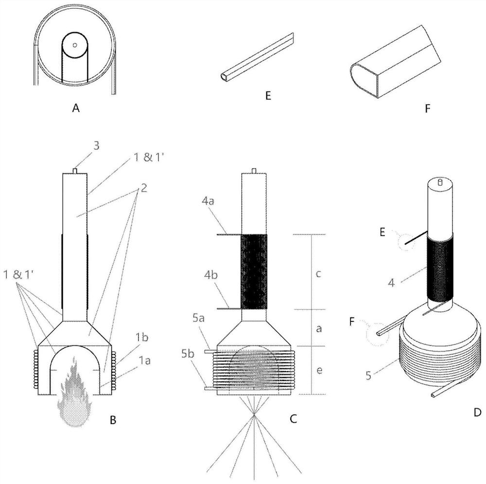
[0044] figure 2 Schematically shows the structural diagram of the heat pipe type heat absorber in Embodiment 1 of the present disclosure.

[0045] like figure 2As shown, the high-temperature heat pipe heat absorber can be composed of a rigid shell 1, an internal high-temperature phase-change working medium 2, a filling port 3, a heat-absorbing fluid pipeline 4 coiled on the outer surface of the shell at the cold end of the heat pipe 1, and a coiled The exothermic fluid pipeline 5 is formed on the outer surface of the tube shell at the hot end of the heat pipe 1 . The inner surface of the shell 1 can be laid or not laid with capillary core 1' according to whether anti-gravity heat transfer is required.

[0046] In this embodiment, the side of the hot end of the heat pipe 1 can be, for example, a cylindrical surface (close to a cylindrical surface) or a cylindrical surface, which is convenient for matching with the heat release fluid pipeline 5 . The end surface of the hot ...

Embodiment 2

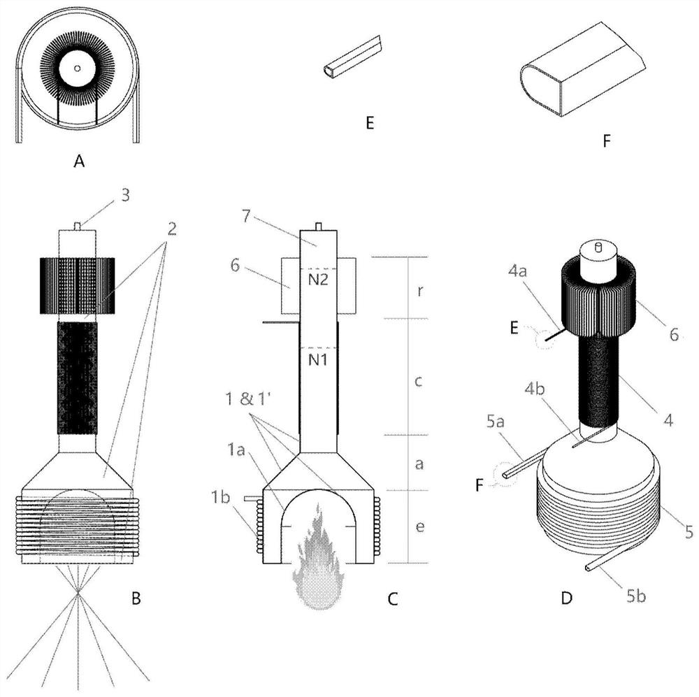
[0050] The structure of the heat pipe heat absorber in Embodiment 2 of the present disclosure is shown as schematically image 3 shown.

[0051] The difference between the heat pipe heat absorber provided in this embodiment and the first embodiment is that: on the side of the heat absorbing fluid pipeline 4 close to the cold end, the heat pipe 1 may also be provided with cooling fins 6 .

[0052] The heat dissipation fins 6 can be closely matched with the outer surface of the heat pipe 1 by means of welding, interference fit, adhesive or high thermal conductivity transition material, for example. When the heat pipe 1 works under normal working conditions, the heat-absorbing fluid has taken out the heat released by the condensation section, so the cooling fins 6 are in a state close to normal temperature and will not dissipate a large amount of heat to the surrounding environment. When the heat-absorbing fluid pipeline 4 or its connected heat-consuming equipment fails or is sh...

Embodiment 3

[0055] The structure of the heat pipe heat absorber in Embodiment 3 of the present disclosure is still as shown image 3 shown.

[0056] The difference between the heat pipe heat absorber provided in this embodiment and the second embodiment is that the cold end of the heat pipe 1 is sealed with a non-condensable gas 7 . The non-condensable gas 7 can also be connected to an external gas storage chamber (not shown in the figure), such as Ar, He, N2, etc. can be used. During the start-up process of the heat pipe 1, the vapor of the phase-change working medium 2 condenses in the condensation section c and returns to the evaporation section e, and the non-condensable gas 7 will be gradually displaced by the phase-change working medium 2 to the cold end of the heat pipe 1 to form a gas plug , and completely cover the radiation + natural convection heat dissipation section r, so that the temperature of the radiation + natural convection heat dissipation section r is low, and the he...


PUM


Abstract

The invention provides a heat pipe type heat absorber. The heat pipe type heat absorber comprises a heat pipe, a phase change working medium, a filling opening, a heat absorption fluid pipeline and aheat release fluid pipeline, wherein the heat pipe is a straight-barrel-shaped heat pipe, one end of the heat pipe is a hot end, and the other end of the heat pipe is a cold end. the phase change working medium is sealed in the heat pipe; the filling opening is formed in the heat pipe and used for filling the phase change working medium into the heat pipe; the heat absorption fluid pipeline is coiled on the outer surface or inside the pipe shell at the cold end of the heat pipe; and the heat release fluid pipeline is coiled on the outer surface or inside the pipe shell at the hot end of the heat pipe. The invention further provides a heat pipe type heat absorber. The heat pipe type heat absorber comprises a heat pipe, a phase change working medium, a filling opening, a condensation sectionpipeline and a heat release fluid pipeline, wherein the heat pipe is an annular heat pipe, and an evaporation section pipeline of the heat pipe is a concave surface which is formed by arranging a plurality of parallel pipe bundles; the phase change working medium is sealed in the heat pipe; the filling opening is formed in the heat pipe and used for filling the phase change working medium into the heat pipe; the condensation section pipeline is connected with the heat preservation section pipeline of the heat pipe to form a loop; and the heat release fluid pipeline and the condensation section pipeline form a cold-end heat exchanger.

Description

technical field [0001] The disclosure relates to the fields of energy power, heat transfer equipment and high-temperature heat utilization, and in particular to a general-purpose high-temperature heat pipe heat absorber. Background technique [0002] In recent years, the clean and efficient utilization of various traditional fossil energies, the complementary and comprehensive utilization of various new energies (such as concentrated solar energy, biomass energy, nuclear energy, etc.) , comprehensive utilization systems supplemented by solar energy with unstable supply, etc., have increasingly become one of the important strategies in the field of energy utilization. In addition, a variety of advanced energy utilization technologies, such as supercritical carbon dioxide (sCO2) or nitrogen (He) closed Brayton cycle power / power generation systems, high-temperature cracking hydrogen production, high-temperature chemical reactors and other cutting-edge technologies are also emer...

Claims


Application Information

Patent Timeline
IPC IPC(8): F28D15/02F28D15/04
CPCF28D15/02F28D15/04
Inventor 李志刚姜玉雁胡和敏谭思聪王涛曾秒
Owner INST OF ENGINEERING THERMOPHYSICS - CHINESE ACAD OF SCI
Learn More