Solar cell and front electrode thereof, and preparation methods and applications thereof

A technology for solar cells and front electrodes, applied in the field of solar cells, can solve problems such as poor collection effect, achieve the effects of reducing metallization recombination, satisfying welding quality, and ensuring the collection effect of front electrodes on carriers

Pending Publication Date: 2021-01-15
TONGWEI SOLAR (ANHUI) CO LTD
View PDF0 Cites 10 Cited by
  • Summary
  • Abstract
  • Description
  • Claims
  • Application Information

AI Technical Summary

Problems solved by technology

[0009] The purpose of the present invention is to overcome the disadvantages that the conversion efficiency of solar cells still needs to be further improved due to the relatively poor collection effect of the front electrodes for existing batteries, and provides a solar cell and its front electrodes, preparation Methods and Applications

Method used


Image

  • Solar cell and front electrode thereof, and preparation methods and applications thereof
  • Solar cell and front electrode thereof, and preparation methods and applications thereof
  • Solar cell and front electrode thereof, and preparation methods and applications thereof

Examples


Embodiment 1

[0072] The preparation method of the solar cell of the present embodiment comprises the following steps:

[0073] 1. Texture making: Use single crystal P-type silicon wafers (158 specifications), and use alkali to make texturing on the front and back to form a textured structure.

[0074] 2. Diffusion: React the silicon wafer after texturing with phosphorus oxychloride and the silicon wafer at high temperature to make the front diffuse to form a PN emitter junction. After diffusion, the square resistance of the thin layer on the front surface is 160Ω / □.

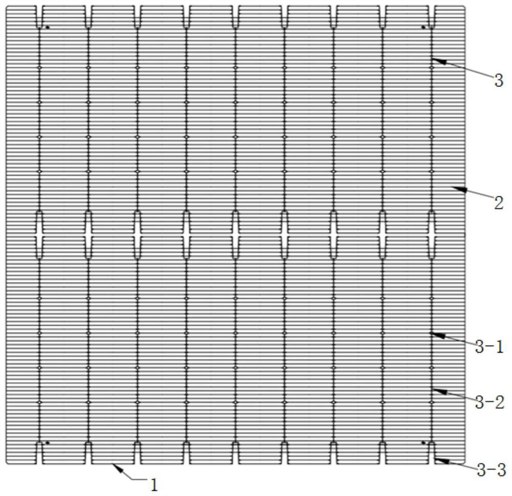
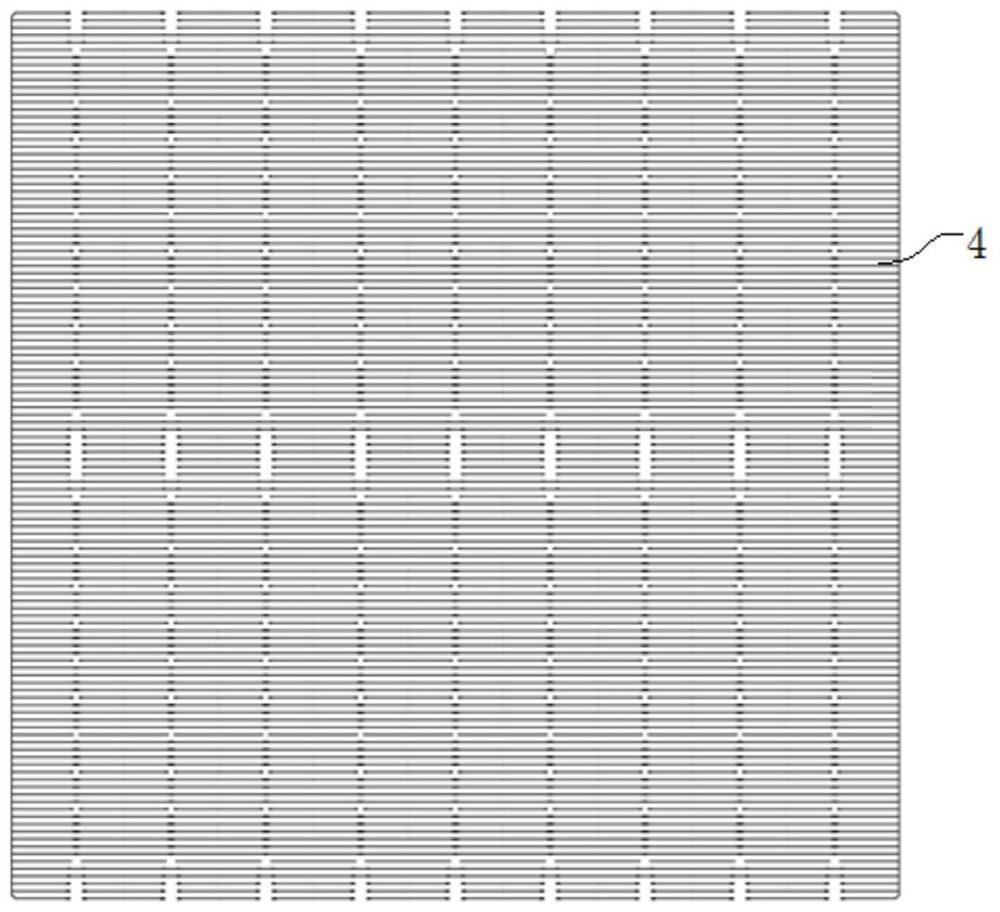
[0075] 3. Laser SE: Using diffused phosphosilicate glass as a phosphorus source, laser doping is carried out on the front side of the diffused silicon wafer and the metallized area corresponding to the positive electrode grid line to form a heavily doped area and a square in the heavily doped area The resistance is between 70Ω / □. The laser SE pattern adopts the pattern without main grid ( figure 2 ).

[0076] 4. Thermal o...

Embodiment 2

[0092] The preparation method of the PERC solar cell of the present embodiment comprises the following steps:

[0093] 1. Texture making: Use single crystal P-type silicon wafers (166 specifications), use alkali to make texturing on the front and back to form a textured structure.

[0094] 2. Diffusion: React the silicon wafer after texturing with phosphorus oxychloride and the silicon wafer at high temperature, so that the front diffuses to form a PN emitter junction. The sheet resistance of the thin layer on the front surface after diffusion was 150Ω / □.

[0095] 3. Laser SE: Using the diffused phosphosilicate glass as the phosphorus source, laser doping is performed on the front side of the diffused silicon wafer and the metallized area corresponding to the positive electrode grid line to form a heavily doped area. The sheet resistance of the heavily doped region is between 60Ω / □. The laser SE pattern adopts the pattern without main grid ( figure 2 ).

[0096] 4. Therma...

Embodiment 3

[0111] The preparation method of the PERC solar cell of the present embodiment comprises the following steps:

[0112] 1. Texture making: Use single crystal P-type silicon wafers (166 specifications), use alkali to make texturing on the front and back to form a textured structure.

[0113] 2. Diffusion: React the silicon wafer after texturing with phosphorus oxychloride and the silicon wafer at high temperature, so that the front diffuses to form a PN emitter junction. The sheet resistance of the thin layer on the front surface after diffusion was 120Ω / □.

[0114] 3. Laser SE: Using the diffused phosphosilicate glass as the phosphorus source, laser doping is performed on the front side of the diffused silicon wafer and the metallized area corresponding to the positive electrode grid line to form a heavily doped area. The sheet resistance of the heavily doped region is between 60Ω / □. The laser SE pattern adopts the pattern without main grid ( figure 2 ).

[0115] 4. Therma...


PUM

PropertyMeasurementUnit
widthaaaaaaaaaa
lengthaaaaaaaaaa
tensile loadaaaaaaaaaa

Abstract

The invention discloses a solar cell and a front electrode thereof, and preparation methods and applications thereof, and belongs to the technical field of solar cells. According to the front electrode of the solar cell, the number of welding spots on a single main grid is 15-70, the width of the single welding spot is 0.4-1.0 mm, and the length of the single welding spot is 0.1-0.6 mm. Accordingto the preparation method of the front electrode, a main grid and an auxiliary grid are printed step by step, specifically, by adopting front silver paste with the solid content of 80-95%, the tinningarea larger than 80% and the tension mean value larger than 1.0 N and not adopting burning through silicon nitride, synchronous printing is carried out on a main grid region, and synchronous printingis carried out on an auxiliary grid region by adopting positive silver paste which has a height-width ratio of 35% or above and can burn through silicon nitride. By adopting the technical scheme of the invention, the collection effect of the positive electrode on carriers can be effectively improved, so that the conversion efficiency of the solar cell can be improved.

Description

technical field [0001] The invention belongs to the technical field of solar cells, and more specifically relates to a solar cell and its front electrode, preparation method and application. Background technique [0002] PERC (Passivated Emitter and Rear Cell) solar cells originated in the 1980s and were developed by the Martin Green research group at the University of New South Wales in Australia. Different from conventional batteries, it adopts the technology of dielectric film passivation and local metal contact on the back surface of the battery, which significantly reduces the recombination rate of the back surface and increases the back reflection of the battery, thereby greatly improving the long-wave effect of the battery. Since 2017, PERC cells have gradually developed into the mainstream high-efficiency solar cell products and technologies in the market. [0003] SE (Selective Emitter, Selective Emitter) technology is to carry out heavy doping on the contact part ...

Claims


Application Information

Patent Timeline
Patent Type & Authority Applications(China)
IPC IPC(8): H01L31/0224H01L31/18B41C1/14B41M1/12B41M1/26
CPCB41C1/145B41M1/12B41M1/26H01L31/022433H01L31/1804Y02E10/547Y02P70/50
Inventor 黄智张林夏伟冉东徐涛翟绪锦谢泰宏
Owner TONGWEI SOLAR (ANHUI) CO LTD
Why Eureka
Try Eureka