Novel SiC MOSFET oscillation suppression circuit applied to half-bridge circuit

A suppression circuit, half-bridge circuit technology, applied in circuits, high-efficiency power electronic conversion, electronic switches, etc., can solve the problems of complex distribution of power loop inductance, increased conduction loss of power devices, complex design, etc., and achieve simple structure and working principle , Reduce switching loss, suppress overvoltage effect

Active Publication Date: 2021-01-15
XI AN JIAOTONG UNIV
View PDF9 Cites 1 Cited by
  • Summary
  • Abstract
  • Description
  • Claims
  • Application Information

AI Technical Summary

Problems solved by technology

Therefore, reducing the power loop inductance is the most direct method to reduce overvoltage and suppress oscillation. When using this method, the distribution of power loop inductance is relatively complicated, and the inductance can be reduced to about 20nH at the maximum, and there will still be a certain overvoltage produce
The snubber circuit is a cost-effective solution to the problem of overvoltage and power oscillation. In the half-bridge structure, the design of the decoupling capacitor is simple and widely used, but it is easy to cause low-frequency oscillation
Some scholars have proposed a high-order RC snubber circuit to solve the low-frequency problem. The performance of the high-order snubber circuit is better, but the design is complicated, and no matter what kind of phase bridge arm snubber is used, the parasitic inductance of the bus bar will be decoupled from the commutation circuit, and the conduction of the power device losses will increase significantly

Method used


Image

  • Novel SiC MOSFET oscillation suppression circuit applied to half-bridge circuit
  • Novel SiC MOSFET oscillation suppression circuit applied to half-bridge circuit
  • Novel SiC MOSFET oscillation suppression circuit applied to half-bridge circuit

Examples


Embodiment Construction

[0020] The present invention is described in further detail below in conjunction with accompanying drawing:

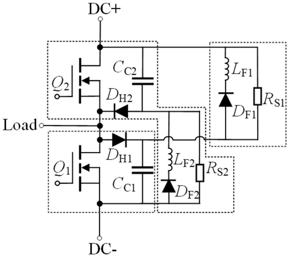
[0021] refer to figure 1 , the novel SiC MOSFET oscillation suppression circuit applied to the half-bridge circuit according to the present invention includes a DC bus, a first SiC MOSFET Q1, a second SiC MOSFET Q2, a first clamping capacitor C c1 , the second clamping capacitor C c2 , the first feedback module, the second feedback module, the load terminal, the first collecting diode D H1 , the second collection diode D H2 and low voltage source; the drain of the DC bus and the second SiC MOSFET tube Q2, and the second clamping capacitor C c2 One end of the first feedback module is connected to one end of the first feedback module, and the source of the second SiC MOSFET Q2 is connected to the second collection diode D H2 The negative pole, the load terminal, the first collector diode D H1 The anode and the drain of the first SiC MOSFET tube Q1 are connected, and...


PUM


Abstract

The invention discloses a novel SiC MOSFET oscillation suppression circuit applied to a half-bridge circuit. The circuit is characterized in that a direct current bus is connected with a drain electrode of a second SiC MOSFET, one end of a second clamping capacitor and one end of a first feedback module, and a source electrode of the second SiC MOSFET is connected with a negative electrode of a second collection diode, a load end, a positive electrode of the first collection diode and a drain electrode of a first SiC MOSFET; the positive electrode of the second collection diode and the other end of the second clamping capacitor are connected with one end of the second feedback module, and the negative electrode of the first collection diode is connected with one end of the first clamping capacitor and the other end of the first feedback module; the low-voltage source is connected with the source electrode of the first SiC MOSFET, the other end of the second clamping capacitor and the other end of the second feedback module, overvoltage can be effectively suppressed by the circuit, and the clamping capacitor in the circuit can feed energy back to the direct current side through theinductance branch and participates in the circuit process only when overvoltage is generated.

Description

technical field [0001] The invention relates to a novel SiC MOSFET oscillation suppression circuit, in particular to a novel SiC MOSFET oscillation suppression circuit applied to a half-bridge circuit. Background technique [0002] SiC MOSFET has excellent performances such as fast switching speed, low on-resistance, and high operating temperature, and is widely used in high-frequency, high-efficiency, and high-power-density power electronic equipment. During the application process, the high-frequency characteristics of SiC MOSFETs often lead to overvoltage and oscillation, which reduces the utilization rate of DC voltage, exacerbates electromagnetic compatibility problems, and reduces the stability of the system. [0003] In power electronic devices, traditional methods to suppress overvoltage and oscillation during switching of SiC MOFETs can be divided into three categories: using gate drive active control, reducing power loop parasitic inductance, and using snubber circ...

Claims


Application Information

Patent Timeline
Patent Type & Authority Applications(China)
IPC IPC(8): H02M1/32H03K17/081
CPCH02M1/32H03K17/08104H03K2217/0036H02M1/0038H02M1/0054H02M1/0048Y02B70/10
Inventor 王来利杨成子李华清于龙洋刘星烁朱梦宇裴云庆
Owner XI AN JIAOTONG UNIV
Why Eureka
Try Eureka