Stent conveying system

A technology of conveying system and guide rail, applied in the field of medical equipment

Active Publication Date: 2021-02-05
APT MEDICAL HUNAN INC
View PDF0 Cites 0 Cited by
  • Summary
  • Abstract
  • Description
  • Claims
  • Application Information

AI Technical Summary

Problems solved by technology

When the covered stent is delivered to the lesion and isolates the lesion, the covered stent needs to be able to isolate the lesion and ensure the smooth flow of important branches. Therefore, this poses a high challenge to the stent delivery system

Method used


Image

  • Stent conveying system
  • Stent conveying system
  • Stent conveying system

Examples


Embodiment Construction

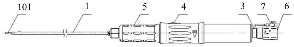
[0058] Please refer to the attached figure 1 , with figure 1 A schematic structural view of the stent delivery system provided by the embodiment of the present application is shown. attached by figure 1 It can be seen that the stent delivery system provided by the embodiment of the present application includes an inner tube 1 , an outer tube 2 , a rail lock component 3 , a paddle component 4 , a handle component 5 , a rear release component 6 and a flushing component 7 . Wherein, the outer tube 2 and the rail lock assembly 3 are set on the outside of the inner tube 1, and the rail lock assembly 3 is sleeved with the paddle assembly 4 and the handle assembly 5, and the end of the rail lock assembly 3 is provided with a rear release assembly 6 and a flushing assembly 7.

[0059] Specifically, the inner tube 1 is a component that fixes and supports the stent graft, and is used to provide passages for the guide wire and the post-release assembly 6 . In the embodiment of the pre...


PUM


Abstract

The invention provides a stent conveying system. The stent conveying system comprises an inner pipe, an outer pipe and a guide rail lock assembly. A shifting piece assembly and a handle assembly sleeve the outer portion of the guide rail lock assembly. The tail end of the inner pipe is fixedly connected with the tail end of the guide rail lock assembly, and a rear release assembly and a flushing assembly are further arranged at the tail end of the guide rail lock assembly. The outer pipe is arranged at the front end of the inner pipe in a sleeving mode, and the tail end of the outer pipe is connected with a connecting rod in the shifting piece assembly through a detachable lock catch structure. The handle assembly sleeves the outer portion of the shifting piece assembly. Internal threads of a rotating handle in the handle assembly are meshed with external threads of a shifting piece in the shifting piece assembly. The stent conveying system is simple in structure and excellent and reliable in performance. In the release process of a covered stent, the covered stent can be stably and accurately released in the mode of combining rotary accurate release and sliding rapid release, andthe problem that due to the fact that the covered stent blocks blood flow for a long time, a blood vessel or an aneurysm is broken can be avoided; and meanwhile, the problem that the release accuracyof the stent is influenced by the wind bag effect can be avoided.

Description

technical field [0001] The invention relates to the technical field of medical devices, in particular to a stent delivery system. Background technique [0002] Aortic aneurysm or dissection is a fatal vascular surgical disease, which may be caused by atherosclerosis, cystic necrosis of the media, syphilis infection, bacterial infection, rheumatic aortitis and trauma, and has a high incidence . [0003] With the continuous development of modern medical technology, a minimally invasive and simple interventional surgery method has been developed for high-risk patients with aortic aneurysm or dissection in recent years, that is, endovascular repair of aortic aneurysm or dissection by using covered stents. In this repair, the covered stent is delivered to the diseased position of the aorta through the minimally invasive incision of the femoral artery under the action of the stent delivery system. This restores normal blood flow in the lumen of the aorta, providing a permanent a...

Claims


Application Information

Patent Timeline
Patent Type & Authority Applications(China)
IPC IPC(8): A61F2/966
CPCA61F2/966
Inventor 成正辉傅泽粮葛新湘沈梦
Owner APT MEDICAL HUNAN INC
Why Eureka
Try Eureka