Electric arc additive manufacturing method with adjustable laser shock

A technology of laser shock and additive manufacturing, which is applied in the fields of electrical digital data processing, instrumentation, design optimization/simulation, etc. It can solve the problem that laser shock parameters and laser shock paths have no reasonable planning and basis, and cannot improve the stress deformation and cracking of the partition, The problem of high power density of laser shock strengthening can achieve the effect of uniform and controllable microstructure, reducing the source of crack propagation and reducing internal defects

Pending Publication Date: 2021-02-05
NANJING UNIV OF SCI & TECH
View PDF1 Cites 7 Cited by
  • Summary
  • Abstract
  • Description
  • Claims
  • Application Information

AI Technical Summary

Problems solved by technology

[0005] However, in view of the above problems, although the existing laser shock assisted arc additive manufacturing method takes advantage of the characteristics of high power density and high accessibility of laser shock strengthening, and can produce deep residual stress affecting layers, it eliminates the forming process to varying degrees. However, there is no reasonable planning and basis for the laser shock parameters and laser shock path. With the increase of the working current during the shock, the energy input to the weld bead surface during the shock is also increa

Method used


Image

  • Electric arc additive manufacturing method with adjustable laser shock
  • Electric arc additive manufacturing method with adjustable laser shock
  • Electric arc additive manufacturing method with adjustable laser shock

Examples


Embodiment 1

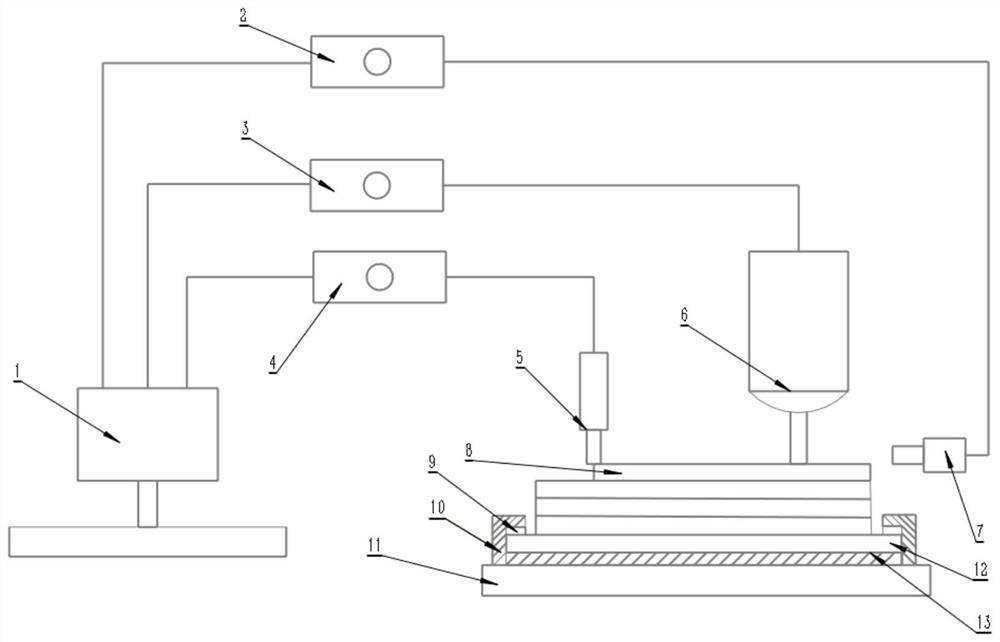
[0104] Such as figure 1 As shown, a method of arc additive manufacturing with adjustable laser shock, the method includes substrate pretreatment, part modeling, planning arc additive path, numerical simulation to obtain stress distribution, setting laser shock parameters and arc additive parameters , collecting the forming temperature, and synchronously forming and laser shock to complete the arc additive component manufacturing. The method steps are specifically:

[0105] Step 1: Grinding the substrate 12 with a steel brush and sandpaper, soaking in an alkali 10% NaOH solution for 10 minutes after grinding, and washing in clean water to remove the residual solution on the surface;

[0106] Step 2: After the substrate 12 is air-dried, it is first cleaned with alcohol and acetone, and then ultrasonically cleaned in the cleaning solution for 10-30 minutes to remove the residue on the surface;

[0107] Step 3: Fix the substrate 12 to the workbench 11, place a preheating device ...


PUM

PropertyMeasurementUnit
Diameteraaaaaaaaaa
Wavelengthaaaaaaaaaa
Pulse energyaaaaaaaaaa

Abstract

The invention belongs to the field of electric arc additive manufacturing, and particularly relates to a laser shock adjustable electric arc additive manufacturing method. The method comprises the following steps: (1) obtaining a machining path of an electric arc additive; (2) setting a temperature threshold; (3) obtaining the stress field distribution of the electric arc additive manufacturing component in real time by adopting a numerical simulation method; (4) setting a laser impact path and setting laser beam parameters; (5) setting technological parameters of arc additive manufacturing, and carrying out layer-by-layer wire arc manufacturing; (6) repeating the steps (3) and (4), and carrying out laser shock treatment on the weld bead to eliminate residual stress; and (7) repeating thestep (5) and the step (6) until the electric arc additive manufacturing component is machined. Numerical simulation and laser shock are combined and applied to electric arc additive manufacturing, sothat residual stress conditions of different areas correspond to laser shock parameters, the optimal laser shock working parameters are adjusted and maintained in real time, and the forming precisionis effectively controlled.

Description

technical field [0001] The invention belongs to the field of arc additive manufacturing, and in particular relates to an arc additive manufacturing method with adjustable laser shock. Background technique [0002] Arc additive manufacturing technology is a kind of 3D printing technology. It melts metal through electric arc, and the metal solidifies rapidly to achieve accumulation. It uses the program to control the movement trajectory of the heat source to form the desired component shape layer by layer. This technology has no strict requirements on external conditions, is suitable for various forming environments and various metal materials, has high forming efficiency, and the wire materials required in the forming process are cheap and easy to prepare, making up for laser additive and electron beam additive manufacturing. Inadequacies of workmanship. In recent years, this process has begun to be applied in the aerospace field, and there is a lot of room for exploration. ...

Claims


Application Information

Patent Timeline
IPC IPC(8): G06F30/17G06F30/23G06T17/00G06F111/10G06F113/10G06F119/08G06F119/14
CPCG06F30/17G06F30/23G06T17/00G06F2111/10G06F2113/10G06F2119/14G06F2119/08
Inventor 彭勇郑仁宗王克鸿周琦廖文健潘垒垒
Owner NANJING UNIV OF SCI & TECH
Why Eureka
Try Eureka