Eureka AIR delivers breakthrough ideas for toughest innovation challenges, trusted by R&D personnel around the world.

Dental implant with osteoinduction structure

A dental implant and osteoinduction technology, applied in dentistry, dental implants, dental prosthetics, etc., can solve the problems of inability to shorten the operation time, weak self-tapping ability, insufficient induction ability and stability, etc., so as to shorten the implantation operation time. , the effect of shortening biocompatibility and ensuring stability

Active Publication Date: 2021-02-09
BEIJING CHUNLIZHENGDA MEDICAL INSTR
View PDF6 Cites 2 Cited by
  • Summary
  • Abstract
  • Description
  • Claims
  • Application Information

AI Technical Summary

Problems solved by technology

However, the induction ability and stability of the implant are insufficient, the self-tapping ability is weak, the stress concentration phenomenon is obvious, and the operation time cannot be shortened.

Method used


Image

  • Dental implant with osteoinduction structure
  • Dental implant with osteoinduction structure
  • Dental implant with osteoinduction structure

Examples


Embodiment 1

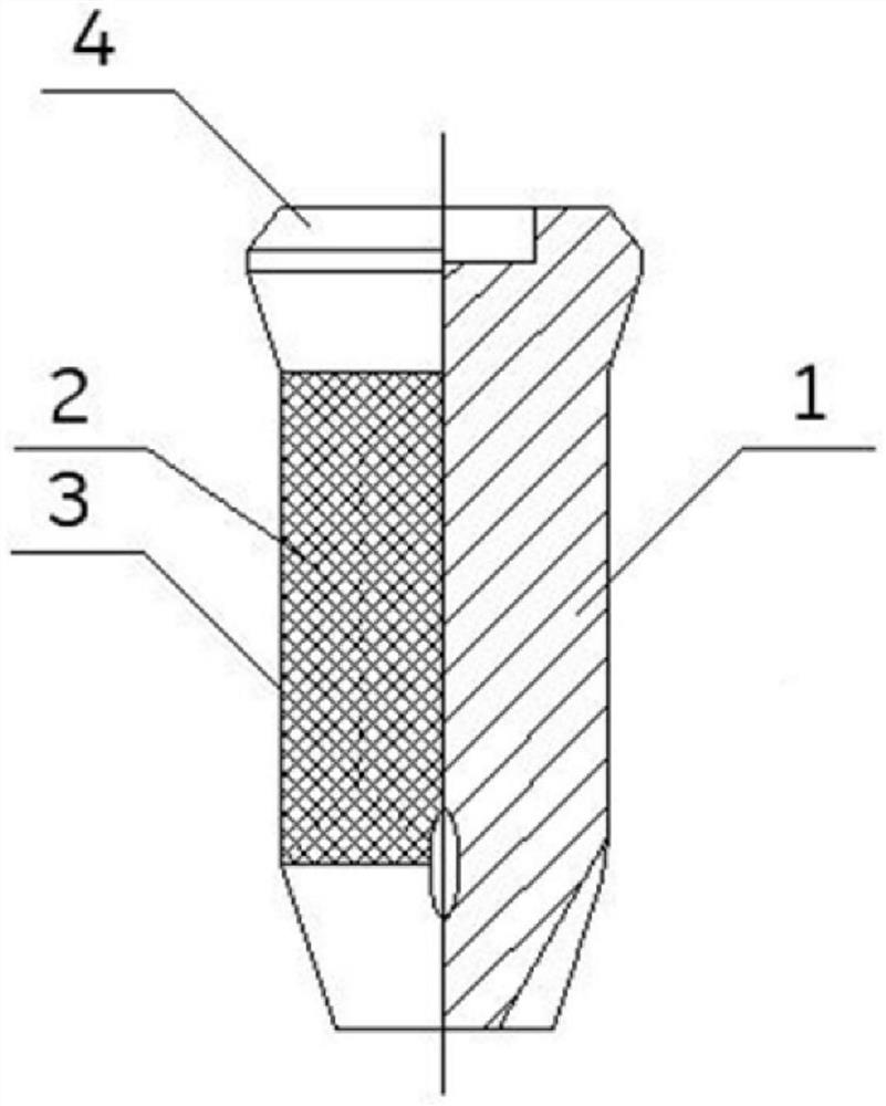
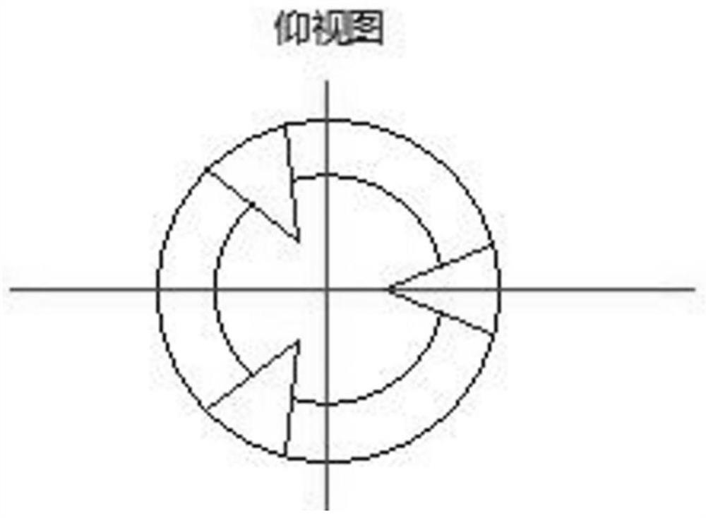
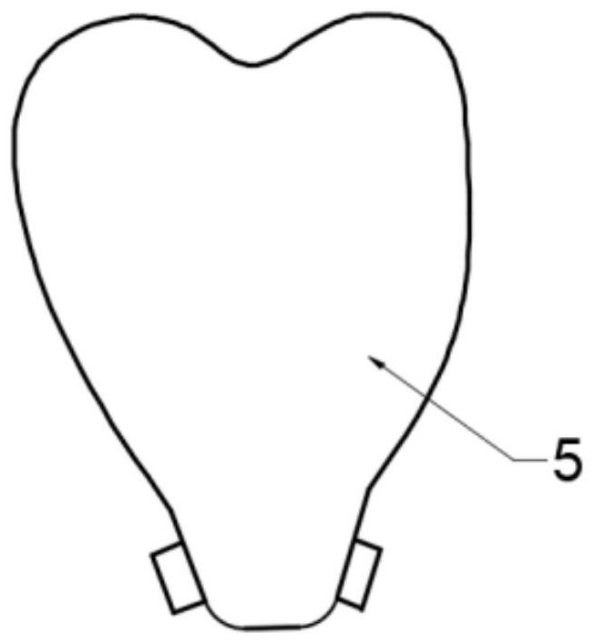
[0028] Please refer to the attached Figure 1-3 , the purpose of this embodiment is to provide a dental implant with an osteoinductive structure, comprising: a solid part 1, a trabecular bone part 2 and a tantalum coating part 3; the solid part 1 has a top and a root, and the top of the solid part 1 The abutment part 4 is integrally formed; the total length from the top to the root of the solid part 1 is 6 mm, the diameter of the cylindrical part of the solid part 1 is 5 mm, and the conical diameter of the root of the solid part 1 is 3 mm. Preferably, the diameter of the abutment part 4 is larger than the diameter of the solid part 1, and the inconsistency between the two diameters can realize stress transfer and avoid stress concentration.

[0029] Specifically, the root of the solid part 1 is conical threaded and has a conical band structure. The root is not only a threaded structure, but the conical band is provided with three cutting edges. The screwing in has a self-tappi...

Embodiment 2

[0034] Please refer to the attached Figure 1-3 , the purpose of this embodiment is to provide a dental implant with an osteoinductive structure, comprising: a solid part 1, a trabecular bone part 2 and a tantalum coating part 3; the solid part 1 has a top and a root, and the top of the solid part 1 The abutment part 4 is integrally formed; the total length from the top to the root of the solid part 1 is 20 mm, the diameter of the cylindrical part of the solid part 1 is 8 mm, and the conical diameter of the root of the solid part 1 is 3-5 mm. Preferably, the diameter of the abutment part 4 is larger than the diameter of the solid part 1, and the inconsistency between the two diameters can realize stress transfer and avoid stress concentration.

[0035] Specifically, the root of the solid part 1 is conical threaded and has a conical band structure. The root is not only a threaded structure, but the conical band is provided with three cutting edges. The screwing in has a self-ta...


PUM

PropertyMeasurementUnit
Wire diameteraaaaaaaaaa
Total lengthaaaaaaaaaa
Diameteraaaaaaaaaa

Abstract

The invention relates to the technical field of medical instruments, and provides a dental implant with an osteoinduction structure. The dental implant comprises a solid part, a bone trabecula part and a tantalum coating part; wherein an integrally-formed base platform part and a root part are arranged at the top of the solid part, the solid part is provided with a rough surface formed by spraying, irregular pore structures are formed on the rough surface, the bone trabecula part is arranged on the irregular pore structures, and the tantalum coating part is arranged on the bone trabecula partof the solid part through 3D printing; and three blade parts with a self-tapping function are arranged on the root part. The dental implant has the beneficial effects that the irregular pore structures are formed on the solid part, so that the contact area with normal sclerotin is extended; a porous bone trabecula structure is beneficial to new bone ingrowth, sufficient space is provided for vascular regeneration and new bone regeneration, and the later-period stability of the implant is guaranteed; and tantalum metal is sprayed to the implant, the osseointegration process is shortened due tothe good biocompatibility, and the clinical osseointegration rate is increased.

Description

technical field [0001] The invention relates to the technical field of medical devices, in particular to a dental implant with an osteoinductive structure. Background technique [0002] Titanium alloy has the characteristics of small specific gravity, high specific strength, low elastic modulus, easy processing and forming, and rich raw material resources. It has now developed into an ideal functional structural material for surgical implants. However, the complex internal environment of the human body will cause corrosion of metal materials and release of toxic elements, thus reducing biocompatibility; for titanium and titanium alloy dental implants, only surface osseointegration can be formed slowly, and rapid bone ingrowth cannot be formed. Make the planting cycle longer, it is difficult to realize immediate planting. In addition, for middle-aged and elderly people with poor alveolar bone quality and osteoporosis, the initial implantation stability of titanium and titani...

Claims


Application Information

Patent Timeline
IPC IPC(8): A61C8/00
CPCA61C8/0024A61C8/0013
Inventor 许奎雪李宁康树靖史春宝李喜旺王振国
Owner BEIJING CHUNLIZHENGDA MEDICAL INSTR
Why Eureka
Eureka Blog
Learn More