Ocean tide-based power generation device with marine organism blocking structure
A technology for power generation devices and marine organisms, which is applied in the direction of ocean energy power generation, electromechanical devices, circuit devices, etc., can solve problems such as single structure, lack of dynamic maintenance and anti-corrosion treatment structures for power generation devices, and inability to block and protect marine organisms, so as to ensure Stability, shortening the efficiency of surface maintenance and cleaning, facilitating powder spilling and improving drying effect
- Summary
- Abstract
- Description
- Claims
- Application Information
AI Technical Summary
Problems solved by technology
Method used
Image

Examples
Embodiment Construction
[0032] The following will clearly and completely describe the technical solutions in the embodiments of the present invention with reference to the accompanying drawings in the embodiments of the present invention. Obviously, the described embodiments are only some, not all, embodiments of the present invention. Based on the embodiments of the present invention, all other embodiments obtained by persons of ordinary skill in the art without making creative efforts belong to the protection scope of the present invention.
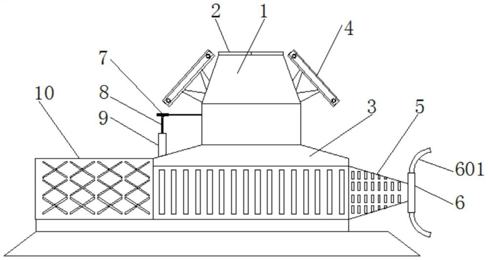
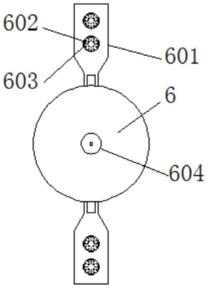
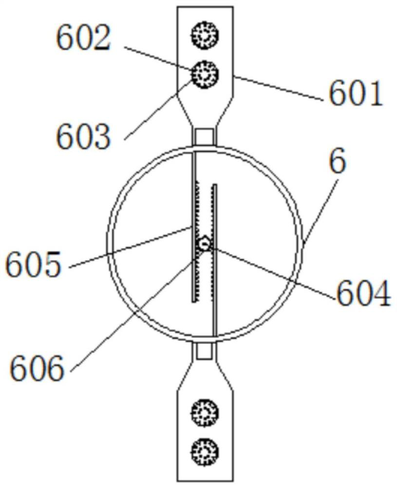
[0033] see Figure 1-9, the present invention provides a technical solution: a power generation device with a marine biological barrier structure based on ocean tides, including a power generation device casing 1, an equipment box door 2, a confluence box 3, a solar panel 4, and a first barrier box 5. Blocking disc 6, belt pulley 7, ball screw 8, sealing gate 9, storage tank 10, gauze sleeve 11, double-rod motor 12, bevel gear 13, mixing tank 14, leakage throu...
PUM
 Abstract
Description
Claims
Application Information