Structure and heat energy recovery system of fluidized bed gasifier

A fluidized bed gasification furnace, heat recovery technology, applied in the gasification process, granular/powdered fuel gasification, chemical industry, etc., can solve the problem of high cost of refractory layer construction and material costs, easy cracks in the refractory layer, Problems such as shedding, slag discharge channel and overheating of the outer wall of the equipment can be solved, and the effect of improving fly ash, reducing equipment investment and easy realization

Pending Publication Date: 2021-02-23
XINNENG ENERGY CO LTD
View PDF0 Cites 0 Cited by
  • Summary
  • Abstract
  • Description
  • Claims
  • Application Information

AI Technical Summary

Problems solved by technology

The traditional gasification furnace uses a refractory layer to insulate the equipment to prevent the outer wall of the gasifier from overheating. The refractory layer can effectively prevent the heat transfer inside the gasifier, and the heat preservation and wear resistance are ideal, but there are the following problems: 1 1. The refractory layer is prone to cracks and falling off during use, which eventually leads to serious problems such as refractory material falling off, blocking the slag discharge channel and overheating the outer wall of the equipment; moreover, the construction and material costs of the refractory layer are high, and it is difficult to maintain after the damage falls off. And its service life generally does not exceed 5 years, which brings great difficulties to production; 2. Since the side wall of the traditional gasifier is equipped with a refractory layer, the overall temperature difference of the gasifier is small, and the gasification The furnace temperature in the furnace is high, which is not conducive to the generation of methane with high calorific value. The content of methane is about 4%. 900°C, so it is necessary to set up waste heat boiler equipment to recover the heat energy in the crude gas; the temperature in the crude gas is high, the airflow speed is fast, and the cyclone separator cannot effectively intercept the fly ash carried in the gas, so it is necessary to set up The filter intercepts the fly ash, and the investment is relatively large, which in turn increases the production cost

Method used


Image

  • Structure and heat energy recovery system of fluidized bed gasifier
  • Structure and heat energy recovery system of fluidized bed gasifier
  • Structure and heat energy recovery system of fluidized bed gasifier

Examples


Embodiment 1

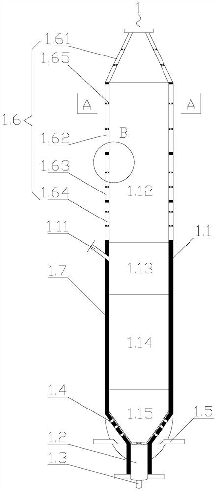
[0024] Embodiment 1: as Figure 1-3 As shown, the structure of a fluidized bed gasification furnace includes a furnace body 1.1, a gas outlet is opened on the top of the furnace body 1.1; a coal inlet 1.11 is opened on the side wall of the furnace body 1.1; A slag discharge channel 1.2 is arranged at the bottom, and a central pipe 1.3 is arranged in the slag discharge channel 1.2; a gas distribution plate 1.4 is fixedly arranged between the slag discharge channel 1.2 and the inner wall of the furnace body 1.1; the furnace body 1.1 below the gas distribution plate 1.4 The side wall is connected with an air inlet pipe 1.5; the furnace body 1.1 is divided into a heat exchange zone 1.12, a dry distillation zone 1.13, a gasification reduction zone 1.14 and a high temperature oxidation zone 1.15 in order from top to bottom, so that the gasification furnace 1 appears The temperature gradient is more conducive to the generation of methane gas, and the content of methane is more than 1...

Embodiment 2

[0026] Embodiment 2: as Figure 4-5 As shown, the embodiment of the present invention further provides a heat recovery system for a fluidized bed gasifier, which includes the above gasifier 1, a water source 2, a steam drum 3, a gas storage tank 4 and a desuperheater 5; a water source 2 It is connected with the water inlet of jacket A1.61 through a pipeline; the water outlet of jacket A1.61 and jacket B1.62 is connected with the water inlet of steam drum 3; the water outlet of steam drum 3 is connected with the inlet of jacket B1.62 The water port is connected; the air outlet of the steam drum 3 is connected with the air inlet of the jacket C1.63; It communicates with the air inlet of jacket D1.64; the air outlet of jacket D1.64 communicates with the air inlet of gas storage cabinet 4 through pipelines; the gas outlet of gas storage cabinet 4 communicates with the air inlet pipe 1.5 of gasifier 1 .

[0027] A first temperature sensor 6 is set at the gas outlet of the gasifie...


PUM


Abstract

The invention discloses a structure and a heat energy recovery system of a fluidized bed gasifier. The fluidized bed gasifier comprises a gasifier body, wherein the interior of the furnace gasifier isinternally divided into a heat exchange area, a dry distillation area, a gasification reduction area and a high-temperature oxidation area from top to bottom in sequence. The system comprises the gasifier, a water source, a steam pocket and a gas storage cabinet, wherein the water source communicates with the water inlet of a jacket A through a pipeline; water outlets of the jacket A and a jacketB communicate with a water inlet of the steam pocket; a water outlet of the steam pocket communicates with a water inlet of the jacket B; an air outlet of the steam pocket communicates with an air inlet of a jacket C; and the air outlet of the jacket C communicates with the air inlet of a jacket D through a pipeline. The structure of the gasifier is simple, can be easily implemented, enables theheat value of raw gas to be higher, reduces maintenance cost and guarantees the normal production of the gasifier. The system disclosed by the invention is simple in connection structure and easy to realize, realizes an automatic control function, recovers heat energy, saves the production cost of raw gas and lowers equipment investment.

Description

Technical field: [0001] The patent of the invention belongs to the technical field of fluidized bed gasification furnace slagging, and specifically relates to a structure of a fluidized bed gasification furnace and a heat recovery system thereof. Background technique: [0002] Fluidized bed gasifiers are mostly used to gasify low-quality coal to produce process crude gas. Because it is rich in methane, it has a high calorific value, so it is used as fuel gas in industry. The traditional gasification furnace uses a refractory layer to insulate the equipment to prevent the outer wall of the gasifier from overheating. The refractory layer can effectively prevent the heat transfer inside the gasifier, and the heat preservation and wear resistance are ideal, but there are the following problems: 1 1. The refractory layer is prone to cracks and falling off during use, which eventually leads to serious problems such as refractory material falling off, blocking the slag discharge ch...

Claims


Application Information

Patent Timeline
Patent Type & Authority Applications(China)
IPC IPC(8): C10J3/56C10J3/60C10J3/72C10J3/74C10J3/80
CPCC10J3/56C10J3/60C10J3/721C10J3/723C10J3/725C10J3/74C10J3/80C10J2300/0936Y02P20/10
Inventor 谭旭刘海建王凤彬
Owner XINNENG ENERGY CO LTD
Why Eureka
Try Eureka