

Application of an ion-conducting membrane containing chlorinated polyvinyl chloride in a flow battery
A technology of chlorinated polyvinyl chloride and ion-conducting membranes, applied in fuel cells, regenerative fuel cells, aqueous electrolyte fuel cells, etc., can solve the problems of membrane stability degradation and achieve increased solubility and molecular bond polarity , high efficiency effect
- Summary
- Abstract
- Description
- Claims
- Application Information
AI Technical Summary
Problems solved by technology
Method used
Image

Examples
Embodiment 1
[0039] Embodiment 1 (preferred)
[0040] Dissolve CPVC (degree of chlorination 72%) and polyvinylpyrrolidone (PVP, degree of quaternization 100%) in an organic solvent, stir fully at 25°C for 48 hours to make a blend solution; wherein the mass concentration of CPVC is 10 %, the mass concentration of PVP is 15%; then pour the prepared CPVC / PVP blend solution directly on a glass plate, and evaporate the solvent at 25°C; finally, immerse the glass plate in water at a temperature of 25°C for 1h , to prepare the CPVC ion-conducting membrane applied in the flow battery, CPVC The thickness of the ion-conducting membrane is 40 μm.
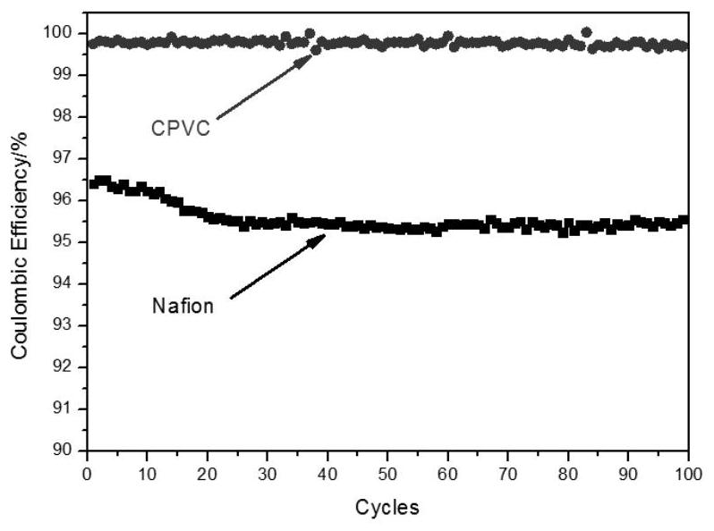
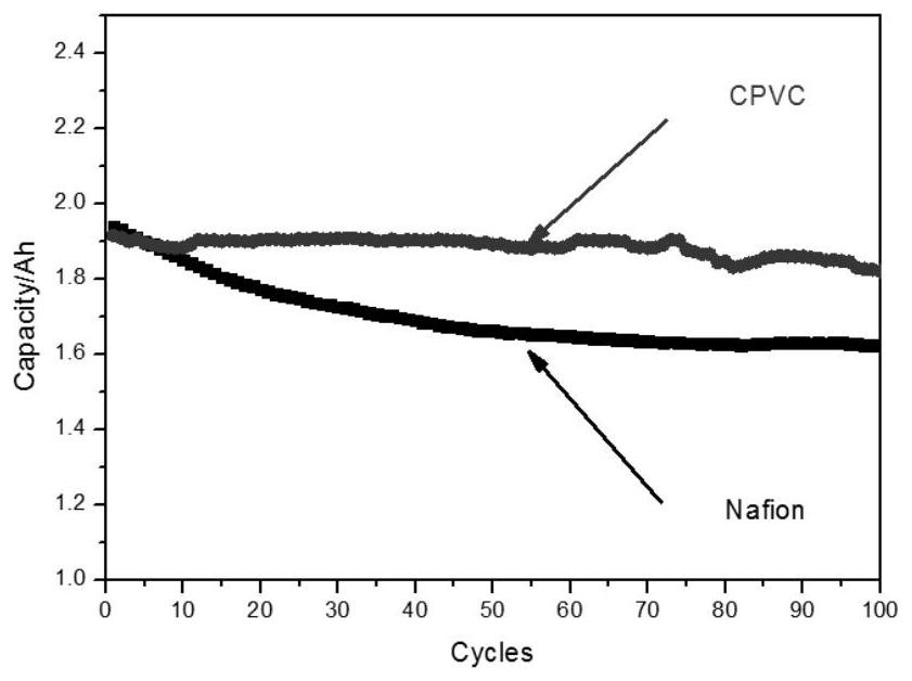
[0041] will be made CPVC The performance of the ion-conducting membrane was tested and compared with the performance of the commercialized perfluorosulfonic acid membrane Nafion 115 membrane. The present invention takes an all-vanadium redox flow battery as an example. Prepared CPVC As shown in Table 1, the surface resistance of the ion-conducting m...
Embodiment 2
[0044] Configure the film-forming solution according to the method described in the above-mentioned Example 1, the difference is that the mass concentration of PVP is 5%, and the prepared CPVC The thickness of the ion-conducting membrane is 40 μm.
[0045] will be made CPVC The performance of the ion-conducting membrane was tested, and compared with the performance of the CPVC ion-conducting membrane prepared in Example 1 and the Nafion 115 membrane. The present invention takes an all-vanadium redox flow battery as an example. Prepared in this example CPVC The surface resistance of the ion-conducting membrane is lower than the surface resistance of the Nafion 115 membrane, but higher than the surface resistance of the CPVC ion-conducting membrane prepared in Example 1, indicating that the decline of the ion-exchange resin content in the CPVC ion-conducting membrane reduces the ion conduction of the membrane rate (table 1); prepared in the present embodiment CPVC Vanadiu...
Embodiment 3
[0048] Configure the film-forming solution according to the method described in the above-mentioned Example 1, the difference is that the mass concentration of PVP is 25%, and the prepared CPVC The thickness of the ion-conducting membrane is 40 μm.
[0049] will be made CPVC The performance of the ion-conducting membrane was tested, and compared with the performance of the CPVC ion-conducting membrane prepared in Example 1 and the Nafion 115 membrane. The present invention takes an all-vanadium redox flow battery as an example. Prepared in this example CPVC The surface resistance of the ion-conducting membrane is lower than the surface resistance of the CPVC ion-conducting membrane prepared in Example 1 and the Nafion 115 membrane, showing that the increase of the ion-exchange resin content in the CPVC ion-conducting membrane has improved the ion conductivity of the membrane (Table 1) ; Prepared in this embodiment CPVC Vanadium ions (VO 2+ ) transmittance is higher tha...
PUM
| Property | Measurement | Unit |
|---|---|---|
| thickness | aaaaa | aaaaa |
| thickness | aaaaa | aaaaa |
| thickness | aaaaa | aaaaa |
Abstract
Description
Claims
Application Information