Environment-friendly flue gas purification treatment device and using method thereof

A flue gas purification and treatment device technology, which is applied in chemical instruments and methods, combined devices, separation methods, etc., can solve the problems that the reaction liquid cannot be recycled, cannot be processed and collected, and can save resources and reduce production costs. Effect

Inactive Publication Date: 2021-03-09
艾银
View PDF1 Cites 2 Cited by
  • Summary
  • Abstract
  • Description
  • Claims
  • Application Information

AI Technical Summary

Problems solved by technology

[0005] The purpose of the present invention is to solve the problem existing in the prior art that during the process of desulfurization, the precipitation generated by the reaction cannot be processed and collected in a timely manner, so that the reaction liquid cannot be recycled. An environmentally friendly flue gas purification treatment device and its application method proposed

Method used


Image

  • Environment-friendly flue gas purification treatment device and using method thereof
  • Environment-friendly flue gas purification treatment device and using method thereof
  • Environment-friendly flue gas purification treatment device and using method thereof

Examples


Embodiment 1

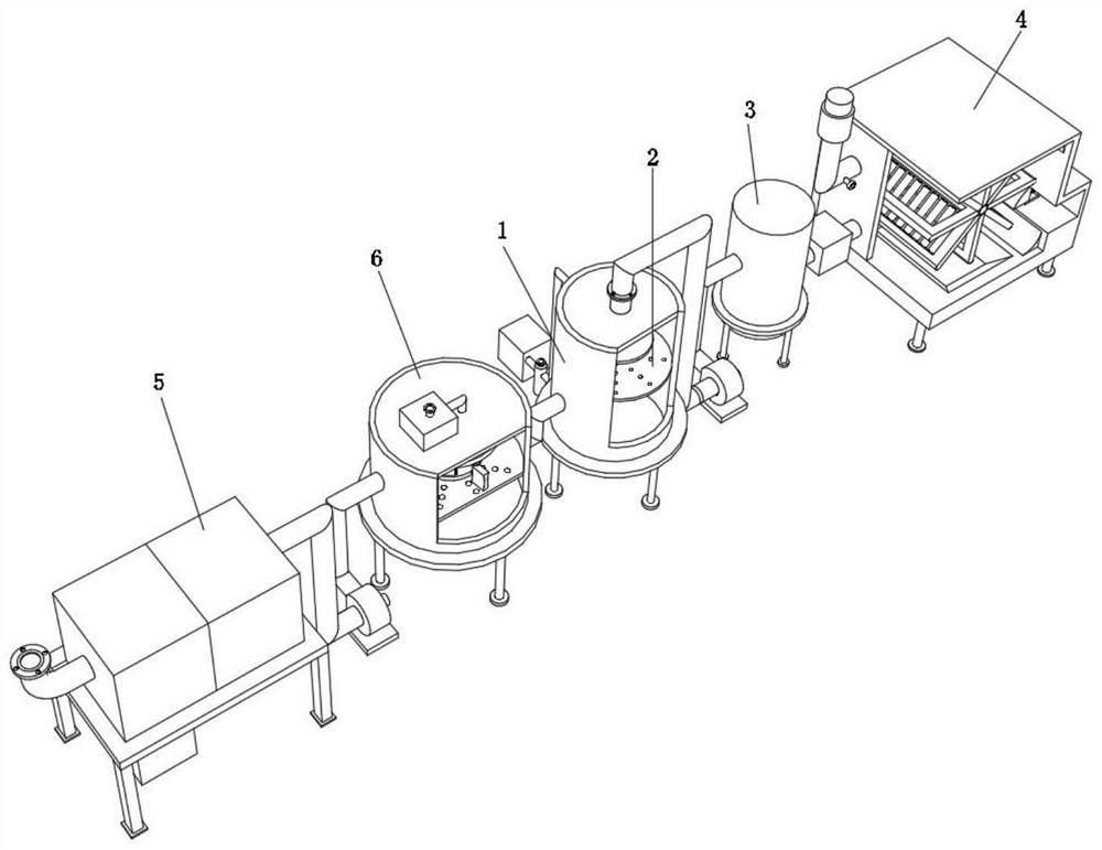
[0045] An environmentally friendly flue gas purification treatment device, such as Figure 1-5 As shown, it includes a desulfurization tower 1, a circulation pump one 22, a circulation pump two 25, a dehydration assembly 26 and a circulation pump three 28. Both the output end and the input end are connected with a connecting pipe 29 through a flange, one end of one of the connecting pipe 29 is fixed with a spray pipe 20 through a flange, and one end of the other connecting pipe 29 is connected with a flange. Calcium hydroxide solvent tank 23, described circulation pump two 25 output ends and input end all are connected with connecting pipe three 24 by flange, and one end of one of said connecting pipe three 24 is connected to calcium hydroxide solvent tank 23 by flange On the side outer wall, one end of the other connecting pipe 3 24 is connected to the return water tank 27 through a flange. The output end and the input end of the circulating pump 3 28 are connected to the con...

Embodiment 2

[0052] A method for using the environmentally friendly flue gas purification treatment device described in Embodiment 1, comprising the following steps:

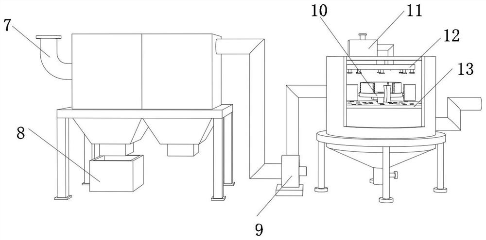
[0053] S1: Lead the flue gas into the bag filter 5 through the flue gas inlet pipe 7;

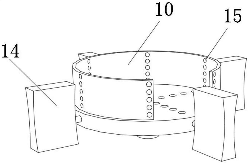
[0054] S2: The flue gas filtered by the bag filter 5 enters the cooling tower 6 through the induced draft fan assembly 9, and the spray pipe 12 performs cooling and spraying on the flue gas;

[0055] S3: The cooled flue gas enters the desulfurization tower 1, and the circulation pump 1 22 and the calcium hydroxide solvent tank 23 are controlled to make the reaction between sulfur dioxide and calcium hydroxide solution;

[0056] S4: The reacted precipitation mixture is dehydrated through the dehydration component 26, and the sulfur dioxide after the precipitation is removed is rewashed into the return water tank 27 to realize the recycling of the calcium hydroxide solution;

[0057] S5: introducing the reacted flue gas into the defogging ...


PUM


Abstract

The invention discloses an environment-friendly flue gas purification treatment device and a using method thereof, and relates to the technical field of flue gas purification treatment devices. In order to facilitate the treatment of precipitates generated after purification, the device specifically comprises a desulfurization tower, a first circulating pump, a second circulating pump, a dehydration assembly and a third circulating pump, a first flow equalizing plate is fixed to the inner wall of the circumference of the desulfurization tower through bolts, fourth connecting pipes are connected to the output end and the input end of the first circulating pump through flanges, and a second spraying pipe is fixed to one end of one fourth connecting pipe through a flange; one end of the otherfourth connecting pipe is connected with a calcium hydroxide solvent tank through a flange; and the using method of the device comprises the following steps: introducing flue gas into a bag-type dustcollector through a flue gas inlet pipe. By arranging the desulfurizing tower, sulfur dioxide contained in flue gas can be treated, and by arranging a back-flow water tank, a water source can be injected into the calcium hydroxide solvent tank by utilizing the secondary circulating pump.

Description

technical field [0001] The invention relates to the technical field of flue gas purification treatment devices, in particular to an environment-friendly flue gas purification treatment device and a use method thereof. Background technique [0002] Smoke is a mixture of gas and smoke and is the main cause of air pollution in residential areas. The composition of the flue gas is very complex. The gas includes water vapor, sulfur dioxide, nitrogen, oxygen, carbon monoxide, carbon dioxide, hydrocarbons, and nitrogen oxides. The smoke includes fuel ash, coal particles, oil droplets, and pyrolysis products. Therefore, The pollution of flue gas to the environment is the compound pollution of various poisons. If the flue gas cannot be effectively treated, it will cause great harm to the environment and human health. [0003] After retrieval, the Chinese patent application number is CN201810487568.9, which discloses an environmentally friendly industrial flue gas comprehensive treat...

Claims


Application Information

Patent Timeline
Patent Type & Authority Applications(China)
IPC IPC(8): B01D53/50B01D53/79B01D53/96B01D53/26B01D53/02B01D50/00
CPCB01D53/502B01D53/504B01D53/79B01D53/96B01D53/26B01D53/02B01D2251/404B01D2251/604B01D2253/102B01D50/10
Inventor 艾银
Owner 艾银
Why Eureka
Try Eureka