
Micro gas turbine combined cycle system with multi-stage Tesla turbine

A micro gas turbine, Tesla turbine technology, applied in combined combustion mitigation, machine/engine, solar heating system, etc., can solve the problems of small occupied space, pressure loss, low pressure drop ratio of Tesla turbine, etc.

Pending Publication Date: 2021-03-16
靳普
View PDF0 Cites 1 Cited by
  • Summary
  • Abstract
  • Description
  • Claims
  • Application Information

AI Technical Summary

Problems solved by technology

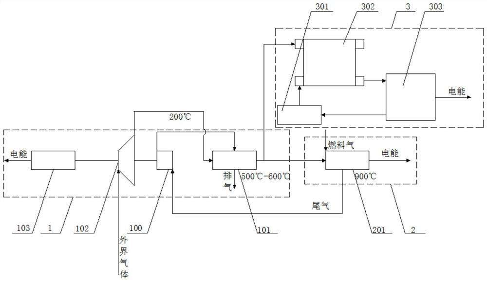
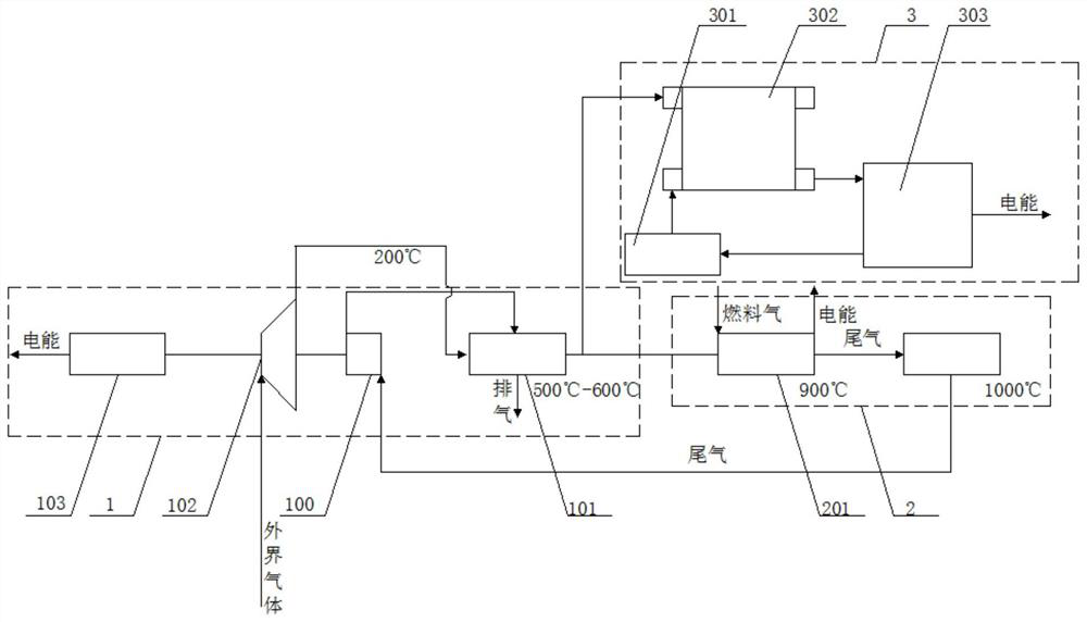
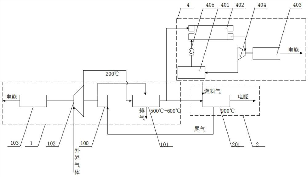
[0008] The technical problem of the present invention is: to overcome the deficiencies of the prior art, to provide a micro gas turbine combined cycle system with a series Tesla turbine, which can further recover and utilize the energy carried in the exhaust gas of the regenerator , and then improve the efficiency of the entire micro gas turbine. At the same time, the circulation system can simultaneously solve the problem of SOFC power generation waste heat and regenerator exhaust waste heat recovery problem, and recycle the heat produced by each link in the system, which can improve the power generation and energy efficiency of the entire system. Recycling efficiency, at the same time, it can be integrated and set up, occupying a small space. In addition, the circulation system achieves efficient use of solar energy through tracking solar energy to improve system power generation efficiency. In addition, the circulation system can solve the problem of existing Tesla turbines falling pressure Low ratio, easy to cause pressure loss and low system efficiency

Method used


Image

  • Micro gas turbine combined cycle system with multi-stage Tesla turbine
  • Micro gas turbine combined cycle system with multi-stage Tesla turbine
  • Micro gas turbine combined cycle system with multi-stage Tesla turbine

Examples


Embodiment Construction

[0055] In describing the present invention, it should be understood that the terms "center", "longitudinal", "transverse", "length", "width", "thickness", "upper", "lower", "front", " Back", "Left", "Right", "Vertical", "Horizontal", "Top", "Bottom", "Inner", "Outer", "Clockwise", "Counterclockwise", "Axial", The orientation or positional relationship indicated by "radial", "circumferential", etc. is based on the orientation or positional relationship shown in the drawings, and is only for the convenience of describing the present invention and simplifying the description, rather than indicating or implying the referred device or element Must be in a particular orientation, be constructed in a particular orientation, and operate in a particular orientation, and therefore should not be construed as limiting the invention. In addition, the features defined as "first" and "second" may explicitly or implicitly include one or more of these features. In the description of the prese...


PUM


Abstract

The invention relates to a micro gas turbine combined cycle system with a multi-stage Tesla turbine. The micro gas turbine combined cycle system with the multi-stage Tesla turbine comprises a micro gas turbine with the multi-stage Tesla turbine, and further comprises at least one of a fuel cell system, a steam power generation system and a solar receiver. The cycle system can further recycle energy carried in exhaust gas of a heat regenerator, so that the efficiency of the whole micro gas turbine is improved, and the recovery problem of SOFC power generation waste heat and exhaust gas waste heat of the heat regenerator can be solved at the same time; heat generated in all links in the system is recycled, so that the power generation and recovery efficiency of the whole system can be improved; meanwhile, integrated arrangement can be achieved, so that the occupied space is small; in addition, efficient utilization of solar energy is achieved through tracking of the solar energy so as toimprove the power generation efficiency of the system; and in addition, the cycle system can solve the problems that an existing Tesla turbine is low in pressure drop ratio, prone to causing pressureloss and low in system efficiency.

Description

technical field [0001] The invention belongs to the technical field of gas turbines and energy recovery and utilization, and in particular relates to a micro gas turbine combined cycle system with multi-stage Tesla turbines. Background technique [0002] The micro gas turbine is a newly developed small heat engine, its stand-alone power ranges from 25 to 300kW, and its basic technical features are radial flow impeller machinery and regenerative cycle. In the prior art, a regenerator is usually used to recycle the exhaust heat of the micro gas turbine, and then the exhaust gas passing through the regenerator is discharged to the atmosphere; however, the exhaust gas passing through the regenerator still has a certain amount of waste heat. In the prior art, There are also methods of recovering and utilizing the energy of the tail gas discharged from the regenerator, usually rotating machines, such as turbines, etc. are used to recover and utilize the energy of the tail gas. Ho...

Claims


Application Information

Patent Timeline
IPC IPC(8): F01K23/00F01K25/00F01K25/08F01K27/00F04B35/04F04B39/06F01D25/12F01K7/02F01K7/16F01D13/02F01D15/10F01D1/36F01D5/06F01D5/02F01D25/16F24S23/70H01M8/04014H01M8/04225H01M8/04223F01B17/04F01B1/08F01B23/10
CPCF01B1/08F01B17/04F01B23/10F01D1/36F01D5/028F01D5/06F01D13/02F01D15/10F01D25/12F01D25/16F01K7/02F01K7/16F01K23/00F01K25/00F01K25/08F01K27/00F04B35/04F04B39/06F24S23/70H01M8/04014H01M8/04268H01M8/04225Y02E10/40Y02E20/16Y02E60/50
Inventor 靳普
Owner 靳普
Learn More