
Denitration process and denitration equipment

A process and denitrification technology, applied in lighting and heating equipment, combustion methods, gas treatment, etc., can solve the problems of high operating temperature, ammonia escape, large amount of catalyst, etc., achieve large adsorption capacity, low energy consumption, and high removal rate Effect

Inactive Publication Date: 2021-03-19
南通斐腾新材料科技有限公司
View PDF10 Cites 1 Cited by
  • Summary
  • Abstract
  • Description
  • Claims
  • Application Information

AI Technical Summary

Problems solved by technology

[0004] In view of the above problems, the present invention provides a new denitrification process and denitrification equipment, aiming to solve the problems of ammonia escape, high operating temperature and large catalyst consumption in the existing SCR denitrification technology

Method used


Image

  • Denitration process and denitration equipment

Examples


Embodiment 1

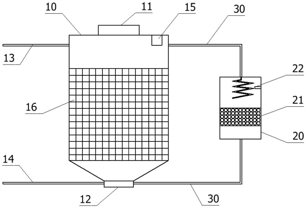
[0050] Open the gas input pipe 14, pass low-concentration sintering flue gas into the adsorption box 10, and use the adsorption material 16 to adsorb and remove the nitrogen oxides in the sintering flue gas. The sensor 15 measures that the nitrogen oxides are less than 50mg / m 3 , then open the gas output pipe 13 to discharge the denitrated gas.

[0051] In this embodiment, modified nano-zeolite is used as the adsorption material, which can effectively concentrate and adsorb nitrogen monoxide and nitrogen dioxide, with large adsorption capacity and high removal rate. Moreover, the adsorption effect has no requirement on the temperature of the sintering gas, and the sintering gas is directly absorbed after passing through, without heating up, and consumes less energy.

Embodiment 2

[0053] Open the gas input pipeline 14, feed high-concentration sintering flue gas into the adsorption box 10, and the adsorption material 16 is saturated. At this time, close the gas input pipeline 14, open the communication pipeline 30 between the adsorption box 10 and the reaction chamber 20, and open Catalytic reduction process, open the burner 22, input heat source and natural gas, control the oxygen content below 5%, carry out oxygen-lean combustion, and raise the atmosphere temperature to 300-400°C; use oxygen-lean combustion and catalyst 21 and some natural gas reaction to obtain carbon monoxide, and then use carbon monoxide to react with nitrogen oxides to generate nitrogen and carbon dioxide, thereby realizing the removal of nitrogen monoxide. It is also gradually desorbed and transported to the reaction chamber 20 for reduction reaction, so that the adsorption material 16 returns to an unsaturated state, and the recycling of the adsorption material 16 is realized; whe...


PUM

PropertyMeasurementUnit
adsorption capacityaaaaaaaaaa

Abstract

The invention discloses a denitration process and denitration equipment, the denitration process uses an adsorption concentration process as a basis, the concentration of nitrogen oxide is measured through a sensor, and when the concentration is lower than a threshold value, gas is directly exhausted; when the concentration is above a threshold, a catalytic reduction process is enabled. The denitration equipment comprises an adsorption box and a reaction chamber, an adsorption material is contained in the adsorption box, can be added from a feeding port in the top end of the adsorption box andis discharged from a discharging port in the bottom end of the adsorption box, the top of the adsorption box is connected with a gas output pipeline, the bottom of the adsorption box is connected with a gas input pipeline, and a sensor is further arranged in the adsorption box. A catalyst is filled in the reaction chamber, a burner is arranged on the side wall of the reaction chamber, and the reaction chamber is communicated with the adsorption box through a connecting pipeline. The denitration process is combined with physical adsorption and chemical reduction processes, different purification processes can be carried out on flue gas with different concentrations and temperatures, particularly, concentration adsorption can be directly used for low-temperature flue gas, temperature risingis not needed, and energy consumption is lower.

Description

technical field [0001] The invention belongs to the technical field of flue gas treatment, and in particular relates to a denitrification process and denitrification equipment. Background technique [0002] NOx is extremely harmful to the ecological environment and human health, and it is difficult to deal with. It has become one of the key pollutants to be controlled in my country. Flue gas denitrification technology is the most important treatment technology in the control measures to reduce NOx emissions at home and abroad. Selective Catalytic Reduction (SCR) is the most widely used denitrification technology in industry. The reaction temperature is generally 300-450°C. Ideally, the removal rate of NOx can reach more than 90%. , is currently the best stationary source NOx control technology. [0003] However, the existing denitrification technology uses ammonia water. In order to ensure the efficient removal of NOx, excess ammonia is generally added, causing ammonia gas...

Claims


Application Information

Patent Timeline
Patent Type & Authority Applications(China)
IPC IPC(8): B01D53/02F23G7/07
CPCB01D53/02F23G7/07F23G7/066B01D2253/108B01D2257/404B01D2258/0283
Inventor 顾鹏飞徐秋霞管慧慧王斐吴子豹
Owner 南通斐腾新材料科技有限公司
Learn More