Optical coherence imaging system capable of eliminating inherent noise and imaging method

An optical coherent imaging and inherent noise technology, applied in the field of medical devices, can solve the problems of reducing signal strength and signal-to-noise ratio, crosstalk, imaging errors, etc., to improve signal strength and signal-to-noise ratio, eliminate inherent noise, and improve accuracy Effect

Active Publication Date: 2021-04-06
JIHUA LAB
View PDF4 Cites 0 Cited by
  • Summary
  • Abstract
  • Description
  • Claims
  • Application Information

AI Technical Summary

Problems solved by technology

[0003] The current technical solution uses natural light for measurement, which is affected by stray light in the environment, and it is easy to introduce imaging errors, which is contrary to the purpose of high-precision measurement
When detected by the optical coherent imaging system that can eliminate inherent noise, it is prone to crosstalk and is easily interfered by stray light in the natural environment, which greatly reduces the signal strength and signal-to-noise ratio, reducing the accuracy of imaging and the safety of surgery

Method used


Image

  • Optical coherence imaging system capable of eliminating inherent noise and imaging method

Examples


Embodiment 1

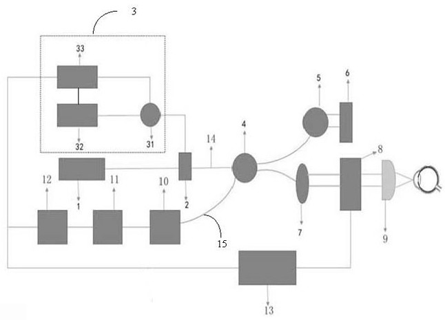
[0035] see figure 1 , is a schematic structural diagram of an optical coherent imaging system capable of eliminating inherent noise provided in Embodiment 1 of the present application, including: a light source (1), and sequentially arranged fiber couplers ( 2), A-scan trigger unit (3), interferometer (4), first collimator lens (5), mirror (6), second collimator lens (7), two-dimensional vibrating mirror scanning unit (8) , a focusing lens (9), an optical fiber polarizing unit (10), a detection unit (11), a data analysis display unit (12) and a control unit (13).

[0036] In some of these embodiments, the fiber polarizing unit (10) is a dichroic polarizer.

[0037] It can be understood that the polarizer is used to obtain polarized light from natural light, and the vibration direction of the polarized light is consistent with the polarization direction of the polarizer. The use of polarized light imaging is not easily affected by stray light in the environment, and it is not...

Embodiment 2

[0055] The present application also provides an imaging method of an optical coherent imaging system capable of eliminating inherent noise, comprising the following steps:

[0056] Step S110: the scanning wavelength beam emitted by the light source (1) is divided into a first beam and a second beam by the fiber coupler (2);

[0057] Step S120: the first light beam enters the A-scan trigger unit (3), and the first light beam entering the A-scan trigger unit (3) passes through the fiber Bragg grating (32) to generate an A-scan trigger with a stable phase signal, the photodetector (33) detects the trigger signal of the stable phase A-scan and transmits it to the optical fiber circulator (31), and the optical fiber circulator (31) sends the stable phase A-scan trigger signal passing back to said photodetector (33);

[0058] Step S130: the second light beam enters the interferometer (4); the interferometer (4) divides the second light beam into an image beam and a reference beam; ...


PUM


Abstract

The invention provides an optical coherence imaging system capable of eliminating inherent noise. The optical coherence imaging system comprises a light source (1) and further comprises an optical fiber coupler (2), an A scanning trigger unit (3), an interferometer (4), a first collimating lens (5), a reflector (6), a second collimating lens (7), a two-dimensional galvanometer scanning unit (8), a focusing lens (9), an optical fiber polarizing unit (10), a detection unit (11), a data analysis and display unit (12) and a control unit (13) which are sequentially arranged in the propagation direction of light beams emitted by the light source (1). According to the optical coherence imaging system capable of eliminating the intrinsic noise, the A scanning trigger unit is arranged to replace an A scanning trigger signal in a signal source to eliminate the intrinsic noise, and the optical fiber polarizing unit is arranged to construct a polarized light imaging structure, so crosstalk is not likely to happen in a detection process, interference of stray light in the natural environment is almost avoided, signal intensity and a signal-to-noise ratio are greatly improved, and imaging accuracy and operation safety are improved.

Description

technical field [0001] The invention belongs to the technical field of medical devices, and in particular relates to an optical coherent imaging system and an imaging method capable of eliminating inherent noise. Background technique [0002] Optical coherence tomography has the characteristics of non-contact, no radiation, high detection sensitivity, and no damage. Optical coherence tomography has become a standard technique for measuring the structure of the human eye in ophthalmic surgery. Femtosecond laser-assisted ophthalmic surgery is an ophthalmic surgery that uses femtosecond laser pulses, optical coherence tomography technology for high-precision detection, and computer precision calculations for trajectory planning to automate and intelligentize several key steps in traditional ophthalmic surgery. . Before, during and after surgery, it is necessary to accurately scan the position and contour of the eye tissue and display the image to the doctor. [0003] The curr...

Claims


Application Information

Patent Timeline
IPC IPC(8): A61B3/10
CPCA61B3/102
Inventor 周辉
Owner JIHUA LAB
Why Eureka
Try Eureka