Supercharge Your Innovation With Domain-Expert AI Agents!

Control method for energy multistage utilization of pneumatic motor

An air motor and energy technology, which is applied in the control field of multi-stage utilization of air motor energy, can solve the problems of compressed gas effective energy loss, compressed gas working ability decline, compressed gas energy loss, etc., to improve flow requirements and response time , Improve the effect of energy utilization

Pending Publication Date: 2021-04-09
BEIJING UNIV OF TECH
View PDF0 Cites 0 Cited by
  • Summary
  • Abstract
  • Description
  • Claims
  • Application Information

AI Technical Summary

Problems solved by technology

Decompression leads to a decrease in the ability of the compressed gas to do work
The exhaust pressure of the air motor is higher than the pressure of the ambient atmosphere, and the exhausted gas also has some ability to do work, and the exhaust gas with a pressure higher than the ambient atmospheric pressure also leads to the loss of energy of the compressed gas carried by the air motor
When the expansion ratio of the air motor is fixed, it will lead to the loss of effective energy of the compressed gas

Method used


Image

  • Control method for energy multistage utilization of pneumatic motor
  • Control method for energy multistage utilization of pneumatic motor

Examples


Embodiment 1

[0029] Embodiment 1: The present invention will be described in further detail below in conjunction with accompanying drawing.

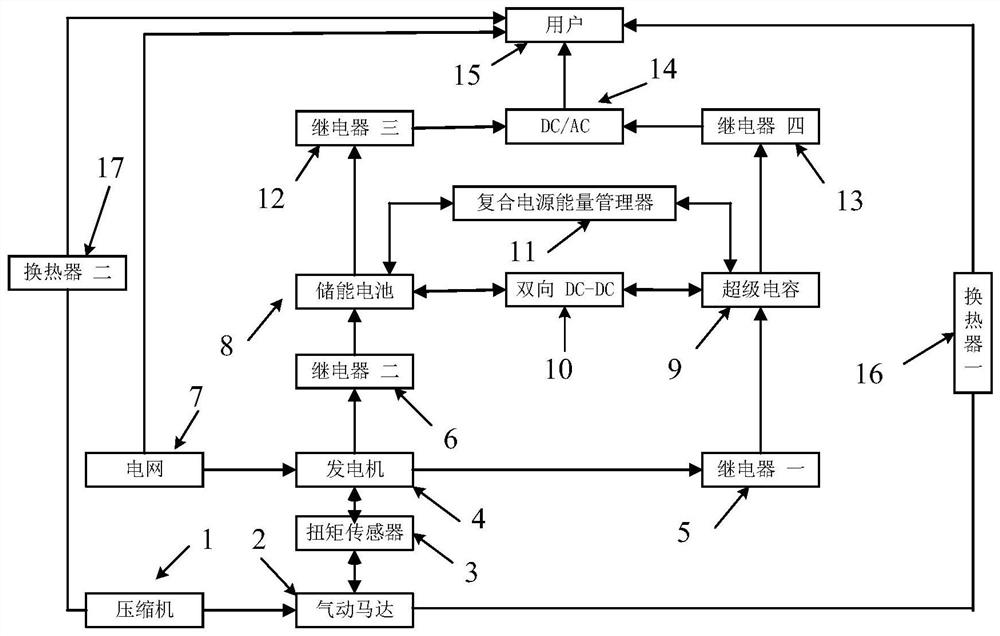
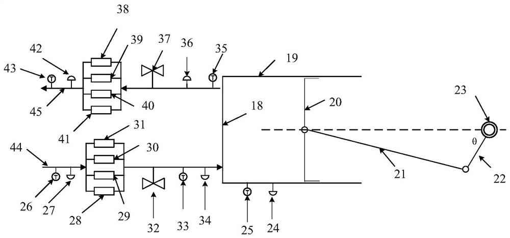
[0030] Such as figure 1 , 2 As shown, a control method for multi-stage energy utilization of an air motor, the technical solution mainly includes an air motor power generation system, an air motor cooling and heating system, and an air motor adjustable expansion ratio and compression ratio system.

[0031] Specifically include: 1. Compressor; 2. Air motor; 3. Torque sensor; 4. Generator; 5. Relay 1; 6. Relay 2; 7. Power grid; 8. Energy storage battery; 9. Super capacitor; 10. Bidirectional DC / DC; 11. Composite power supply energy manager; 12. Relay three; 13. DC / AC; 14. Relay four; 15. User; 16. Evaporator one; 17. Evaporator two; 18. Cylinder head; 19. Cylinder; 20. Piston; 21. Connecting rod; 22. Crankshaft; 23. Encoder; 24. Pressure sensor one; 25. Temperature sensor one; 26. Temperature sensor two; 27. Pressure sensor two; 28. Solenoid valve 1...


PUM


Abstract

The invention discloses a control method for energy multistage utilization of a pneumatic motor, and belongs to the field of energy conservation and emission reduction. According to the control method, the flow requirement of an air supply system of the pneumatic motor is improved and the response time of the air supply system of the pneumatic motor is prolonged through parallel connection of electromagnetic valves; the variable expansion ratio and the variable compression ratio of the pneumatic motor are achieved by adjusting the opening time and the closing time of the different electromagnetic valves, and the energy utilization rate of the pneumatic motor is increased. The pneumatic motor converts energy of compressed air into continuously rotating mechanical energy and has the advantages of being low in price, convenient to operate and use, easy to maintain, capable of achieving stepless speed change and the like. When the pneumatic motor is used as an expansion machine, the exhaust temperature of the pneumatic motor is lower than the environment temperature, so that the exhaust of the pneumatic motor has the potential of refrigeration, and the exhaust of the pneumatic motor can be used for refrigeration when a user needs to cool; and when the pneumatic motor serves as a compressor, the temperature of the compressed air rises while the pneumatic motor generates the compressed air, and therefore the pneumatic motor can supply heat to the user when serving as the compressor.

Description

technical field [0001] The invention relates to a control method for multi-stage energy utilization of an air motor, which belongs to the field of energy saving and emission reduction. Background technique [0002] Energy is an important material basis for human survival and development, and it is also a powerful driving force for national economic development. Compressed air energy storage is an energy storage method that has attracted much attention because of its advantages such as long life, large capacity, low cost, and less environmental pollution. However, compared with batteries, etc., the cycle efficiency of compressed air energy storage is relatively low . The compressed gas flows out from the gas storage tank and flows into the cylinder after being decompressed by the pressure reducing valve. Decompression results in a decrease in the ability of the compressed gas to do work. The exhaust pressure of the air motor is higher than the pressure of the ambient atmos...

Claims


Application Information

Patent Timeline
Patent Type & Authority Applications(China)
IPC IPC(8): F01B29/04F01B23/10F01B31/12F01B31/14F01B25/10F01B31/00F04B35/04H02J7/34F25B9/06F24D15/00
CPCF01B29/04F01B23/10F01B31/12F01B31/14F01B25/10F01B31/00F04B35/04H02J7/34H02J7/345F25B9/06F24D15/00
Inventor 许永红张红光杨富斌杨一帆闫栋任景
Owner BEIJING UNIV OF TECH
Features
  • R&D
  • Intellectual Property
  • Life Sciences
  • Materials
  • Tech Scout
  • Unparalleled Data Quality
  • Higher Quality Content
  • 60% Fewer Hallucinations
Learn More