Eureka AIR delivers breakthrough ideas for toughest innovation challenges, trusted by R&D personnel around the world.

Laser scanning device and scanning method capable of changing the size and morphology of light spot at laser focus position

A laser scanning device and focal position technology, applied in optics, optical components, instruments, etc., can solve the problems of high energy loss rate, non-adjustable spot size and shape, complex optical path structure, etc.

Pending Publication Date: 2021-04-09
NANJING UNIV OF SCI & TECH +1
View PDF6 Cites 8 Cited by
  • Summary
  • Abstract
  • Description
  • Claims
  • Application Information

AI Technical Summary

Problems solved by technology

The optical waveguide reflection shaper introduces an optical waveguide into the optical system, so that the incident laser beam is reflected multiple times inside the system, so that the laser beam is evenly distributed, and its internal optical path structure is complex; the compound eye uniform beam shaper is the incident laser beam. Segmentation and superposition have a high energy loss rate; the telescope system with a diaphragm only isolates the peripheral low-energy area, and only retains the central high-energy area, which belongs to pseudo-uniform distribution, and the spot size and shape of the laser focus position Neither adjustable

Method used

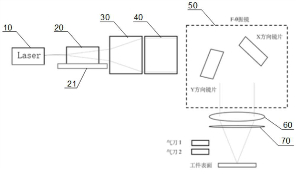
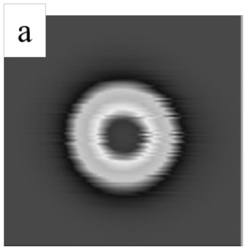
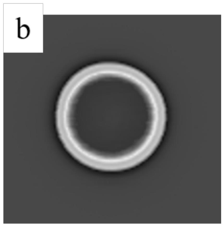

Image

  • Laser scanning device and scanning method capable of changing the size and morphology of light spot at laser focus position
  • Laser scanning device and scanning method capable of changing the size and morphology of light spot at laser focus position
  • Laser scanning device and scanning method capable of changing the size and morphology of light spot at laser focus position

Examples


Embodiment Construction

[0035] In order to better understand the technical content of the present invention, specific embodiments are given together with the attached drawings for description as follows.

[0036] Aspects of the invention are described in this disclosure with reference to the accompanying drawings, which show a number of illustrated embodiments. Embodiments of the present disclosure are not necessarily intended to include all aspects of the invention. It should be appreciated that the various concepts and embodiments described above, as well as those described in more detail below, can be implemented in any of numerous ways, since the concepts and embodiments disclosed herein are not limited to any implementation. In addition, some aspects of the present disclosure may be used alone or in any suitable combination with other aspects of the present disclosure.

[0037] combine figure 1 The laser scanning device of the exemplary embodiment shown can change the spot size and shape of t...


PUM


Abstract

The invention provides a laser scanning device and scanning method capable of changing the size and morphology of a light spot at a laser focus position, and the device comprises: a laser source, a collimating lens group, a beam expanding lens group and a micro-lens array, wherein the micro-lens array has a micro-lens optical unit with N*N array arrangement and is used for carrying out the homogenization of an expanded light beam, forming uniform light intensity distribution output, and changing light spot energy into flat top distribution; a scanning galvanometer system; and a field lens system, wherein the collimating lens group is installed on a mobile platform capable of moving back and forth in the optical axis direction, the size of a light spot at a laser focus position is changed through back-and-forth movement of the mobile platform, and the laser focus is located at the center of the incident focus of the beam expanding lens group and the micro-lens array. According to the laser scanning device and the scanning method, stable light spot output with the size and shape of the light spots at the laser focus position adjustable is provided, energy distribution of the laser light spots is changed into uniform flat top distribution from traditional Gaussian distribution, and light intensity homogenization treatment is achieved.

Description

technical field [0001] The invention relates to the technical field of laser beam scanning, in particular to a laser scanning device and a scanning method capable of changing the size and shape of a spot at a laser focus position. Background technique [0002] In the fields of laser processing and laser reconstruction such as laser scanning, polishing, welding, cutting, surface shaping, marking, and laser cladding processing, the output of high-power laser beams is used to achieve optical processing such as collimation and convergence. The surface is processed accordingly. At present, the laser beam output by the laser is usually a circular parallel beam with a Gaussian energy distribution. After the beam is directly focused by the collimating lens and hits the processing surface, the energy of the circular, rectangular, and linear spots formed It is also a Gaussian distribution, the energy of the center of the spot is too high, and the energy of the periphery of the spot i...

Claims


Application Information

Patent Timeline
Patent Type & Authority Applications(China)
IPC IPC(8): G02B27/09G02B26/10
CPCG02B27/0927G02B27/0961G02B27/0905G02B27/0933G02B26/10
Inventor 刘捷王克鸿彭勇邢飞徐国建唱丽丽
Owner NANJING UNIV OF SCI & TECH
Why Eureka
Eureka Blog
Learn More