
Processing method of 3D printing silicon carbide reflector

A technology for printing silicon carbide and a processing method, which is applied in the processing field of optical components, and can solve the problems of uneven distribution of phase materials, large differences, and difficult processing and molding.

Active Publication Date: 2021-04-16
NAT UNIV OF DEFENSE TECH
View PDF9 Cites 5 Cited by
  • Summary
  • Abstract
  • Description
  • Claims
  • Application Information

AI Technical Summary

Problems solved by technology

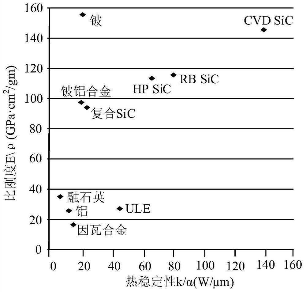
[0003]Due to the brittle texture and high hardness of silicon carbide, it is difficult to process and shape, especially some complex structures (such as porous structures designed for lightweight) is difficult to shape
The traditional method of preparing silicon carbide has the following disadvantages: the preparation accuracy is low, and it is difficult to prepare parts with complex shapes, especially complex parts such as mirrors, which require precise processing molds and supporting processing tools, resulting in high preparation costs
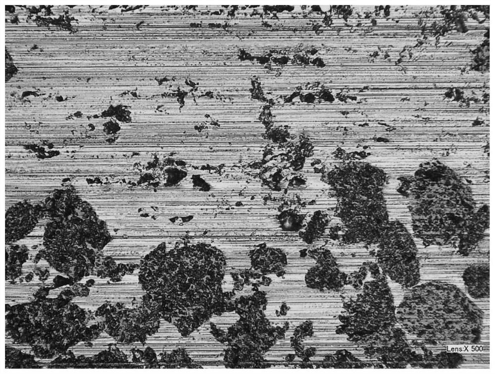
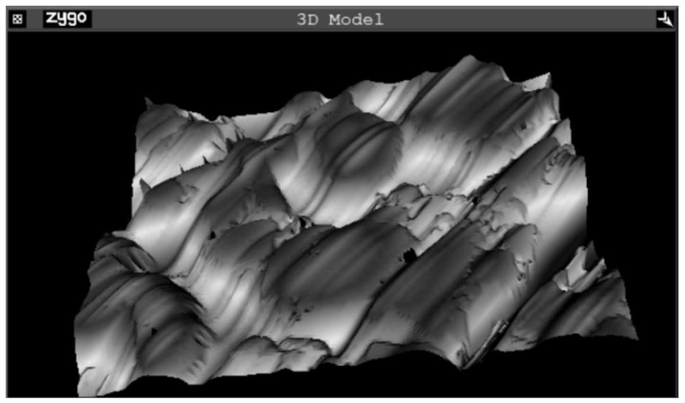
[0004] There are many components in 3D printing silicon carbide optical materials, and the distribution of materials in each phase is uneven, such as Figure 2, the physical properties of Si and SiC with the highest content are quite different. The removal rate of SiC is faster than that of SiC, so micro-steps are formed at the junction of the two phases, such as Figure 3 shows that the unevenness of the surface of silicon carbide leads to the low quality of the optical surface obtained after direct polishing
There are also impurities such as printing binders in 3D printing silicon carbide optical materials, and the porosity is high, which affects the density of the material, such as Figure 4, the presence of impurities and pores will have an adverse effect on improving the quality of the mirror surface

Method used


Image

  • Processing method of 3D printing silicon carbide reflector
  • Processing method of 3D printing silicon carbide reflector
  • Processing method of 3D printing silicon carbide reflector

Examples


Embodiment Construction

[0044] The present invention will be further described in detail below in conjunction with the accompanying drawings and specific embodiments.

[0045] The workpiece in this embodiment is a 3D printed silicon carbide plane mirror with a diameter of 100 mm. The present invention will be further described below in conjunction with the accompanying drawings and specific preferred embodiments, and the combined polishing method used in the present invention will be further described.

[0046] Such as Figure 5 As shown, the steps of the 3D printing silicon carbide mirror combined polishing processing method in this embodiment include:

[0047] 1) Carry out surface grinding on the printed silicon carbide blank workpiece, remove the pits and protrusions on the surface of the workpiece, and obtain a flat workpiece surface;

[0048] 2) Carry out small grinding head grinding and rough polishing on the workpiece to be processed to obtain a reflector surface that meets the initial surfac...


PUM


Abstract

The invention discloses a processing method of a 3D printing silicon carbide reflector. The processing method comprises the steps of grinding a 3D printing silicon carbide workpiece to obtain a flat workpiece surface, then carrying out grinding and rough polishing to obtain a reflector surface meeting the initial surface shape and surface quality requirements, and then carrying out magnetorheological modification and conformal smoothing on the reflector surface in an iteration mode until the index requirements are met. According to the method, the problem that multi-phase structures are not uniformly removed in the processing course of the 3D printing silicon carbide reflector can be solved, the defects of the surface shape and the surface quality of an existing silicon carbide reflector polishing technology are overcome, ultra-precision processing of the 3D printing silicon carbide reflector is realized, the processing surface shape precision is high, and the surface quality is good.

Description

technical field [0001] The invention relates to a processing technology of an optical element, in particular to a processing method of a 3D printed silicon carbide mirror. Background technique [0002] With the rapid development of space astronomical optics and satellite remote sensing technology, more and more stringent requirements are put forward for the working band, imaging resolution, thermal stability and system weight of the optical system. Selecting a suitable mirror material is of great significance to meet these indicators. Considering the manufacturing, launching, operating costs and working environment of the space optical system, the following aspects must be considered in the selection of space mirror materials: 1) isotropy, Dimensional stability; 2) The mirror body can be polished and can be coated with a high-reflectivity film. Good polishability is the basic requirement for mirror materials, especially when used for visible light detection. Good polishabili...

Claims


Application Information

Patent Timeline
Patent Type & Authority Applications(China)
IPC IPC(8): B24B1/00
CPCY02P10/25
Inventor 胡皓徐超彭小强关朝亮戴一帆杨启霖
Owner NAT UNIV OF DEFENSE TECH
Learn More