Equipment for incineration treatment and resource application of ammonium-sulfate-containing waste liquid
A recycling and waste liquid technology, applied in the chemical industry, can solve the problems of excessive content, high dust content, sulfuric acid mist and aerosol particles exceeding the standard, etc.
Active Publication Date: 2021-04-16
中国船舶集团有限公司第七一一研究所 +1
7 Cites 2 Cited by
AI-Extracted Technical Summary
Problems solved by technology
However, the current ammonium sulfate recovery equipment has many problems, such as prone to dew point corrosion, high dust content affecting the quality of ammonium su...
Method used
According to the equipment of the present invention for incineration treatment of sulfur-containing ammonium waste liquid and resource utilization, the waste heat boiler adopts the structure of membrane wall cavity plus convection heating surface, and the inorganic salts in the molten state in the high-temperature flue gas are in the membrane wall The cavity is cooled to a temperature below the melting point, thereby solidifying into solid particles, preventing the molten inorganic salts from directly solidifying and bonding to the subsequent convective heating surface, and increasing the temperature of the heat exchange tube wall to effectively avoid the dew point corrosion of acid gas.
Continue to refer to Fig. 1, mist eliminator 160 is arranged on the downstream of absorption tower 131 and is communicated with the washing section 141 of absorption tower 131, and the flue gas flowing out from the top of water washing section 141 enters after removing mist eliminator 160 and removes wherein liquid droplets and/or aerosol particles. For example, sulfuric acid mist can be removed. The demister 160 is preferably a wet electrostatic demister. As a result, the discharge concentration of sulfuric acid mist and aerosol particles can be avoided from exceeding the standard, thereby avoiding the tailing phenomenon of white smoke during discharge.
Preferably, continuing to refer to FIG. 1 , the waste heat recovery device 120 also has a steam drum 125, which communicates with the membrane wall of the waste heat boiler 121 and the convective heating surface 124 (or in other words, the steam drum 125 also communicates with the convective heating surface 124). The heat exchanger on the surface 124 is connected) to form a fluid circulation and enhance the heat exchange effect.
[0070] Wherein, the incinerator 110 is used to receive sulfur-containing ammonium waste liquid, fuel and air and burn to produce flue gas. The incinerator 110 preferably adopts an adiabatic furnace, and the combustion-supporting fan 111 provides the incinerator 110 with the air required for fuel combustion and high-temperature oxidation and decomposition of waste liquid. The shell of the incinerator 110 needs to have a certain temperature, and its temperature is...
Abstract
The invention discloses equipment for incineration treatment and resource application of ammonium-sulfate-containing waste liquid. The equipment comprises an incinerator, a waste heat recovery device and a desulfurization device. The incinerator is used for combusting the waste liquid to generate flue gas. The waste heat recovery device comprises a waste heat boiler, the waste heat boiler comprises a first membrane type wall cavity communicating with the incinerator and a second membrane type wall cavity located at the downstream position of the first membrane type wall cavity, and the upper portions of the first membrane type wall cavity and the second membrane type wall cavity communicate with each other. The first membrane wall cavity is used for reducing the temperature of the flue gas to be lower than the melting point of inorganic salt, a convection heating surface is arranged in the second membrane type wall cavity, and the second membrane type wall cavity is used for reducing the temperature of the flue gas to a first preset temperature. The desulfurization device is located at the downstream position of the waste heat recovery device, communicates with the waste heat recovery device and is used for converting SOX into ammonium sulfate and recovering the ammonium sulfate. According to the equipment for incineration treatment and resource application of the ammonium-sulfate-containing waste liquid, acid dew point corrosion of the heating surface of the boiler can be avoided.
Application Domain
Electrostatic separationDispersed particle separation +4
Technology Topic
Ammonium sulfateProcess engineering +8
Image
Examples
- Experimental program(1)
Example Embodiment
[0063]In the following description, a large number of specific details are given to provide more thorough understanding of the present invention. However, it will be apparent to those skilled in the art that the present invention may be implemented without one or more of these details. In other examples, in order to avoid confusion with the present invention, it is not described in the technical features known in the art.
[0064]In order to completely understand the invention, a detailed description will be made in the following description. It should be understood that these examples are provided to make it unconventional of the present invention to provide ordinary skill in the art. Obviously, the implementation of embodiments of the present invention is not limited to special details familiar to those skilled in the art. BEST MODE FOR CARRYING OUT THE INVENTION The present invention can also have other embodiments in addition to these detailed descriptions.
[0065]It should be noted that the terms used herein are merely intended to describe embodiments, and are not intended to limit exemplary embodiments in accordance with the present invention. As used herein, unless the context further clearly indicates that the singular form is intended to include multiple forms. Furthermore, it should be understood that when the terms "including" and / or "comprising" are used in this specification, it indicates that the features, whole, steps, operations, elements, and / or components, but do not exclude presence or Additional one or more other features, overall, steps, operations, components, components, and / or their combinations thereof.
[0066]The predetermined number of "first" and "second" cited in the present invention is merely an identifier without any other meaning, such as a particular order, and the like. Further, for example, the term "first component" itself does not imply the presence of "second components", the term "second component" itself does not imply the presence of "first components".
[0067]It should be noted that the terms "on", "" under "," front "," post "," left "," right "," inside "," external ",", ",", ",", ",", "," inside ", and similar expressions are intended to Not limited.
[0068]An exemplary embodiment according to the present invention will now be described in more detail with reference to the accompanying drawings.
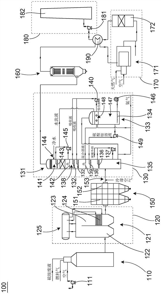
[0069]Please refer tofigure 1, According to a preferred embodiment of the present invention, an apparatus 100 comprising a thiommonium tutene waste liquid and a resource-based application comprises an incinerator 110, a residual heat recovery apparatus 120, a dust collector 150, a desulfurization device 130, a debris 160, a denitration apparatus 170, preheating heat exchanger 190 and discharge device 180.
[0070]Among them, the incinerator 110 is used to receive a thiommonium taunt, fuel and air and combust to generate flue gas. The incinerator 110 is preferably adopted by a heat insulating furnace, a fuel-saving fan 111 provides a fuel combustion and a high temperature oxidation decomposition of the waste furnace 110. The incinerator 110 housing requires a certain temperature, which is preferably higher than the dew point temperature of the flue gas, i.e., is generally greater than 120 ° C. Alternatively, the incinerator 110 housing can be designed in the heat wall to avoid the acid gas SO in the abutment of the waste liquid.X(SO2And / or SO3Deep point corrosion.
[0071]The outer surface of the incinerator 110 housing is preferably provided that the protective cover (not shown), the shield and the housing are formed to form an air interlayer, which is capable of facilitating the safety maintenance of the operator while ensuring the temperature of the housing.
[0072]The remaining heat recovery device 120 is located downstream of the incinerator 110, which includes a waste heat boiler 121 configured as a double cavity structure. Specifically, the remaining heat boiler 121 includes a first membrane wall cavity 122 and a second membrane wall cavity 123. The first membrane wall cavity 122 is in communication with the incinerator 110 to receive high temperature flue gas and reduce the temperature of the flue gas to the melting point of the inorganic salt contained in the flue gas.
[0073]The second membrane wall cavity 123 is located downstream of the first membrane wall cavity 122, and the upper portion of the second membrane wall cavity 123 communicates with each other, that is, partially Spacer. The second membrane wall cavity 123 is provided with a pair of flow absorbing surface 124, and the second membrane wall cavity 123 is used to reduce the temperature of the flue gas to the first preset temperature. For example, the first preset temperature can be 270 to 350 ° C. The above pair flow receiving surface 124 can be a surface of a heat transfer tube.
[0074]The remaining heat boiler 121 recovers part of the heat of the high temperature flue gas, and can produce steam above 3.8 MPa to ensure that the temperature of the flow-conditioned surface 124 is greater than SO.XDew point temperature.
[0075]According to the incineration of the incineration of the incineration of anemonium thiommonium thrasic waste liquid and the resource-based apparatus, the remaining heat boiler uses the structure of the membrane wall empty cavity to the heat surface, and the inorganic salt of the melted state in the high temperature flue gas is in the membrane wall. Cool to the temperature below the melting point, thereby solidifying into solid particles, avoiding the inorganic salt of the molten state directly solidifies on the subsequent pair of flow, while increasing the temperature of the heat transfer tube effectively avoids the dew point corrosion of the acid gas.
[0076]Preferably, continue with referencefigure 1The remaining heat recovery device 120 also has a vapor bag 125, and the film wall of the air bag 125 and the remaining heat boiler 121 communicates with the flow absorbing surface 124 (or the air bag 125 is also in communication with the heat exchanger having the flow absorbing surface 124). Form fluid circulation and enhance heat exchange effect.
[0077]The dust collector 150 is located downstream of the remaining heat recovery device 120, and the dust collector 150 is preferably constructed as a double cavity structure. That is, it can have a first dust collecting chamber 151 and a second dust collecting chamber 152 disposed in series. More preferably, the dust collector 150 is configured as an electrostatic dust collector. The bottom of the dust collector 150 has a gray (not shown), and then removes most of the particulates from the flue gas re-dust collector 150 from the remaining heat recovery device 120 and then continues to flow downstream. This reduces the particulate matter in the flue gas to improve the quality of the received ammoniumulmonium.
[0078]The desulfurization device 130 is located downstream of the remaining heat recovery device 120, which uses an ammonia method desulfurization process. Since the preferred desulfurization reaction temperature in the demandulfurization process of the ammonia method is generally not higher than 60 ° C, it is necessary to cool the flue gas entering the desulfurization device 130.
[0079]Preferably, the cooling air inlet 153 can be provided on the line between the dust collector 150 and the desulfurization device 130 to pass air into the line, thereby adjusting the temperature of the flue gas entering the desulfurization device 130 to the second preset temperature. . For example, the second preset temperature can be 160 to 200 ° C.
[0080]The desulfurization device 130 mainly includes an absorption tower 131 and an oxidation tank 133. The absorption tower 131 is from bottom to concentration segment 135, the absorption section 138, and the water wash section 141. The concentration segment 135 and the absorption segment 138 are spaced from the first separator 139, and between the absorption segments 138 and the water scrubbing sections 141 are spaced apart from the second partition 142. The first separator 139 and the second separator 142 are each configured to have an upwardly extending air passage, and the top of the air passage is also preferably provided in a liquid cover to avoid the liquid from the air passage to the lower layer. A liquidket can be formed between the tower wall of the first separator 139 and the absorption segment 138, and the second partition plate 142 can also form a liquid groove between the tower wall of the water wash section 141.
[0081]The concentration section 135 is in communication with the dust collector 150 to receive a flue gas having the second preset temperature and cool the flue gas to a temperature suitable for the desulfurization reaction.
[0082]The cooling fumes immediately rises into the absorption segment 138, and the absorbing segment 138 is provided with an absorbent shower unit 132, which can be provided for two to five layers. In the illustrated embodiment, two layers of absorbent shower shower 132 are provided. The absorption of the shower shower 132 contains absorption liquid to the flue gas (which can make the ammonium ammonium ammonium ammonium) to the flue gasXTransformed into ammonium sulfite. The resulting bisulfite is dissolved in a sprayed liquid to form a mixed solution comprising ammonium sulfite and / or ammonium sulfite and temporarily present in a liquid tank of the absorption section 138.
[0083]The upper portion of the oxidation tank 133 is provided with an aminocharine 148, and the absorption section 138 is in communication with the amino chamber 148. Specifically, the amino chamber 148 is in communication with the liquid tank of the absorption section 138 to receive a mixed solution from the absorption section 138.
[0084]The amino chamber 148 is also in communication with the ammonia pipeline to receive ammonia gas, so that the ammonia gas is reacted with ammonium hydrogen sulfite in the mixed solution, and partial sulfite is converted to ammonium sulfite, which in turn converts the mixed solution to have pre-proposed The absorption liquid of the pH is set. Alternatively, the pH of the absorption liquid can also be adjusted by replenishing the ammonia water in the amino chamber 148. The absorbent liquid can re-enter the absorption section 138 for spray. For example, the absorption of the shower shower 132 can be communicated with the amino chamber 148 via the absorption cycle pump 140.
[0085]Further, the ammonia pipe can also communicate into the concentration section 135, input to the concentration section 135, in particular to input ammonia gas into the liquid in the concentration section 135, so that the pH of the liquid of the concentrated segment is not too low , Avoid corrosion of the bottom of the absorption tower 131.
[0086]The oxidation tank 133 also includes a oxide chamber 147 located below the amino chamber 148, and the oxide chamber 147 can communicate with the amino chamber 148 via the via the bottom of the amino chamber 148. A portion of the concentration large (or high) in the mixed solution of the amino chamber 148 can be subjected to the oxidation chamber 147 by the via the bottom hole at the bottom of the amino chamber 148.
[0087]The bubble 134 is provided in the oxidation chamber 147, and the bubble 134 is drumped into the air in the oxidation chamber 147 in the action of the air fan 146 such that ammonium sulfate and / or ammonium sulfite in the mixed solution are oxidized into sulfuric acid. Ammonium, and the oxidation chamber 147 reaches a concentration of ammonium sulfate solution can be then transferred to the concentration section 135 by a line. For example, ammonium sulfate solution can be delivered to a concentrated shower member 136 of the concentration section 135 by the conveying cycle pump 149.
[0088]The low concentration of the upper layer (or left amino chamber 148) remaining in the oxidation tank 133 can be used as an absorbing solution after adjusting the pH (in-gas). A gas line is also provided on the top of the oxidation tank 133, which is preferably in communication to the concentration segment 135 to deliver the remaining air of the oxidation reaction and excess ammonia gas to the concentration section 135 and the flue gas.
[0089]Returns the concentration segment 135, which is provided with a concentrated shower device 136 (shown in the illustrated embodiment), which can pass the concentration circulating pump in communication with the concentration section 135. 137 forms a circulating spray, using heat exchange of flue gas and ammonium sulfate solution to cool the flue gas, and ammonium sulfate solution can be concentrated. The concentration of concentrated ammonium sulfate solution can be rejected by the concentration segment 135 for recovery. For example, the concentrated ammonium sulfate solution can be delivered to the user's sulfuriumonmonium.
[0090]Watching the water washing section 141, the flue gas passes through the absorption section 138 continues to flow upward to the water wash section 141. Because of the smoke in this stage, there must be a small amount of NH.3Therefore, it is necessary to remove it in the water washing section 141. To this end, the water washing shower 143 is provided in the water wash sections 141, and the water washing shower 143 is connected to the liquid tank of the water washing section 141 via the water washing pump 145 to form a water washing cycle. An inlet port 144 is also provided on the absorption segment 138 to supplement water in water washing sections 141. The liquid tank of the water wash section 141 is also in communication with the oxidation tank 133, and the water washing liquid in the liquid tank may be temporarily present in the liquid tank. For example, the washing solution can be delivered to the amino chamber 148. The water washing liquid enters the oxidation tank 133 can supplement the liquid in the oxidation tank 133 to maintain the level of the liquid level (the liquid level in the oxidation tank 133 is preferably higher than the amino chamber 148), thereby maintaining the water balance within the desulfurization device 130.
[0091]SO from the top of the water washed 141XThe content can reach emission requirements.
[0092]Continue referencefigure 1The pecker 160 is disposed downstream of the absorption column 131 and communicated with the water wash sections 141 of the absorption tower 131, and the flue gas flowing out from the top of the water wash section 141 enters the droplets and / or aerosol particles of the dewer 160. . For example, the sulfuric acid flexion can be removed. The pecker 160 is preferably a wet electrostatic deperorizer. Thereby, the discharge concentration of sulfate droplets and aerosol particles can be avoided, and thereby avoiding the white smoke tail of the emissions.
[0093]The denitrifer 170 is disposed downstream of the inverter 160 for removing NO in the flue gas.X. Make emissions more environmentally friendly.
[0094]Specifically, the denitrifer 170 includes a hot dam 171 and an SCR reactor 172 located downstream of the hot dam 171. Since the temperature of the flue gas flowing out from the defective 160 is low, about 50 to 55 degrees Celsius, a temperature is much lower than the temperature of the denitrifination reaction, and thus the flue gas to enter the SCR reactor 172 needs to be heated.
[0095]To this end, the auxiliary fuel (natural gas) and the combustion air enter the hot blast furnace 171 combustion to heat the flue gas to the third preset temperature, i.e., the temperature suitable for the SCR reaction. For example, the third preset temperature can be 250 to 300 ° C.
[0096]Ammonia inlet is also provided at the exit of the hot dam 171. The ammonia gas is used as a reducing agent, and the air is injected into the pipeline of the hot blast furnace 171 after mixing, and the flue gas is fully mixed into the SCR reactor 172, and the denitrifination reaction occurs under the action of the catalyst, thereby removing NOX.
[0097]Continue referencefigure 1In a preferred embodiment, the incineration of the incineration of the present invention treats the amonmiumonmonium thrason waste liquid and the resource application can also provide a preheating heat exchanger 190. The line extending from the outlet of the deserial 160 passes through the preheating heat exchanger 190 and then communicates into the denitration device 170. The line extending from the outlet of the SCR reactor 172 also passes through the preheating heat exchanger 190. The flue gas from the derogator 160 and the flue gas flowing out from the SCR reactor 172 are heat exchange in the preheating heat exchanger 190 to recover the energy of the part of the part, and reduce the energy consumption of the device.
[0098]The flue gas flowing from the SCR reactor 172 is reduced to 120 to 140 ° C after heat exchange, and then the discharge device 180 is discharged into the atmosphere. The discharge device 180 can include a blower 181, which is disposed at the end of the entire device to ensure that the integrity of the flue gas passage inside the device is in a negative pressure operating state, effectively avoiding toxic and harmful corrosive gases to the external environment. The air blower 181 delivers the flue gas that has been met to the chimney 182 to the atmosphere.
PUM


Description & Claims & Application Information
We can also present the details of the Description, Claims and Application information to help users get a comprehensive understanding of the technical details of the patent, such as background art, summary of invention, brief description of drawings, description of embodiments, and other original content. On the other hand, users can also determine the specific scope of protection of the technology through the list of claims; as well as understand the changes in the life cycle of the technology with the presentation of the patent timeline. Login to view more.