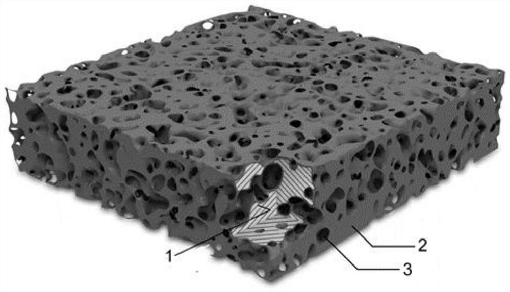
Photocatalytic device taking porous ceramic as carrier as well as preparation method and application thereof

A technology of porous ceramics and photocatalysis, applied in chemical instruments and methods, physical/chemical process catalysts, chemical/physical processes, etc., can solve the problems of difficult separation and recycling of powdered photocatalysts

Pending Publication Date: 2021-04-20
BEIJING INSTITUTE OF GRAPHIC COMMUNICATION
View PDF6 Cites 1 Cited by
  • Summary
  • Abstract
  • Description
  • Claims
  • Application Information

AI Technical Summary

Problems solved by technology

Most of the existing photocatalytic materials are in the form of powder, and it is difficult to separate and recycle the powdery photocatalyst after the catalytic reaction

Method used


Image

  • Photocatalytic device taking porous ceramic as carrier as well as preparation method and application thereof

Examples


preparation example Construction

[0023] In the present invention, the preparation method of the porous ceramic carrier preferably includes the following steps:

[0024] Mix silica gel and water for hydrothermal reaction to obtain porous ceramic carrier;

[0025] In the present invention, the hardness of the silicone gel is preferably 80-140 g, the viscosity range is preferably 0.01-1.50 mJ, and the wire drawing length is preferably 0.58-5.21 mm. In the present invention, the mass ratio of the silica gel to water is preferably (85-95):(5-15), more preferably 90:10. The present invention has no special requirements on the mixing method, and a mixing method well known to those skilled in the art can be used.

[0026] In the present invention, the pressure of the hydrothermal reaction is 20-1050MPa, preferably 100-500MPa; the temperature of the hydrothermal reaction is 200-500°C, preferably 350-400°C; the time of the hydrothermal reaction 10 to 240 min, more preferably 60 to 120 min. In the present invention, ...

Embodiment 1

[0053] In the reaction kettle, the porous ceramic carrier was grown by hydrothermal-hot static pressing method: the silica gel and water were mixed at a mass ratio of 9:1, the pressure of the autoclave was set to 110MPa, and the hydrothermal reaction was carried out at 360°C for 110min; After the hydrothermal reaction ends, a porous ceramic carrier is obtained; the surface and interior of the obtained porous ceramic carrier have microcavity holes, and the bulk density is 0.9g / cm 3 The pore volume is 1.2cm / g; the pore diameter range of the microcavity is 200-500nm; the thickness of the porous ceramic carrier is 200μm.

[0054] Mix glacial acetic acid, distilled water, and absolute ethanol at a volume ratio of 3:1:3, and stir evenly to form the first solution; mix butyl titanate, glacial acetic acid, and absolute ethanol at a volume ratio of 5:1:6 to form the second solution. Second solution; slowly add the first solution to the second solution under the condition of stirring in...


PUM

PropertyMeasurementUnit
thicknessaaaaaaaaaa
densityaaaaaaaaaa
pore sizeaaaaaaaaaa

Abstract

The invention provides a photocatalytic device taking porous ceramic as a carrier as well as a preparation method and application of the photocatalytic device, and relates to the technical field of photocatalytic devices for degrading organic pollutants in water. The photocatalytic device provided by the invention comprises a porous ceramic carrier and TiO2 / BiOCl composite film photocatalytic layers located on the surface of the porous ceramic carrier and in micro-cavity holes in the porous ceramic carrier. Compared with the conventional TiO2 photocatalysis, the photocatalysis device taking the porous ceramic as the carrier provided by the invention has the advantages that the TiO2 / BiOCl composite film photocatalysis layer on the surface of the porous ceramic carrier and in micro-cavity holes inside the porous ceramic carrier is doped with flaky BiOCl nano-powder with a relatively large interlayer space, so separation of photo-induced electrons and hole pairs of the TiO2 / BiOCl composite film photocatalysis layer is facilitated; moreover, an absorption band can be subjected to red shift, the photoresponse range is expanded, and the photocatalytic degradation efficiency and the solar energy utilization rate are improved. After the catalytic reaction, the device is easy to separate from sewage and recycle.

Description

technical field [0001] The invention relates to the technical field of photocatalytic devices for removing organic matter in water, in particular to a photocatalytic device with porous ceramics as a carrier, a preparation method and application thereof. Background technique [0002] Photocatalytic technology is widely used in the treatment of organic pollutants in water environment. Use solar energy to catalyze the degradation of organic pollutants in water to meet the needs of sustainable energy development. Among many semiconductor materials, TiO 2 is the most commonly used photocatalyst, but TiO 2 Electron-hole pairs can only be formed under ultraviolet light irradiation, and the solar energy utilization rate is less than 5%; and TiO 2 Photogenerated electrons and holes are easy to recombine, resulting in low quantum yield in the photocatalytic process, and a single TiO 2 The use of photocatalysts has limitations, often by combining other nanomaterials with TiO 2 Com...

Claims


Application Information

Patent Timeline
Patent Type & Authority Applications(China)
IPC IPC(8): B01J27/135B01J35/02B01J35/04C02F1/30C02F101/30C02F101/38
Inventor 李烨刘儒平赵慧庆张会灵肖莹莹王梦珠
Owner BEIJING INSTITUTE OF GRAPHIC COMMUNICATION
Why Eureka
Try Eureka