Non-glass device for connecting laser gyroscope with exhaust station

A technology of laser gyroscope and connecting device, which is applied to lasers, laser parts, Sagnac effect gyroscopes, etc., can solve the problems of polluting the laser gyroscope and damaging the precision vacuum devices in the exhaust table.

Pending Publication Date: 2021-05-14
江西驰宇光电科技发展有限公司
View PDF0 Cites 2 Cited by
  • Summary
  • Abstract
  • Description
  • Claims
  • Application Information

AI Technical Summary

Problems solved by technology

In addition, due to the presence of glass in the system, glass breakage cannot be avoided during the long-term "aging" process, resulting in air leakage into the vacuum system, contaminating

Method used


Image

  • Non-glass device for connecting laser gyroscope with exhaust station
  • Non-glass device for connecting laser gyroscope with exhaust station
  • Non-glass device for connecting laser gyroscope with exhaust station

Examples


Example Embodiment

[0032]Example one

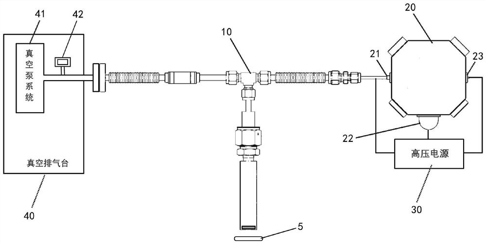
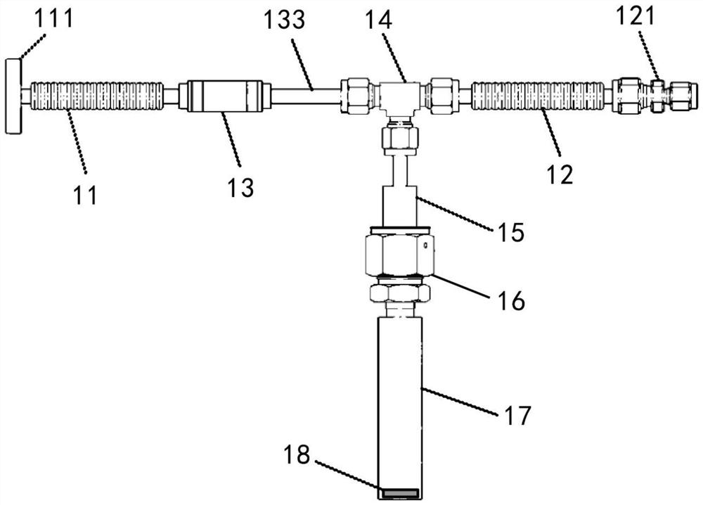
[0033]Such asFigure 1-6 As shown, a non-glass device for laser gyro 2 is connected to the discarisher, including a connecting device assembly 1, a laser gyro 2, a high voltage power source 3, a vacuum discharge station 4, and the activation coil 5. Wherein, the connecting device assembly 1 includes a bellows 11, a bellows two 12, a partition assembly 13, a three-way joint 14, a pair of tubing 15, a sealing joint 16, a storage tank 17, a suction agent 18; the bellows The flange interface 111 of the 11 11 is mounted to the flange of the vacuum air supply stage 4, thereby forming the flexible connection of the connecting device assembly 1 and the vacuum discharge station 4, and is used in the vacuum air supply stage 4 to generate a negative pressure. The vacuum pump system 41 is provided with a vacuum meter 42 on the line between the flange interface 111, and the measurement accuracy of the vacuum gauge 42 is 1 × 10⁻⁷The other end of the bellows 11 is connected to the ...

Example Embodiment

[0039]Example 2

[0040]This example differs from the embodiment one in the first embodiment in that the connection device assembly 1 further includes a split ring 19, the split ring 19 is a cyclic body made of a magnetic alloy material, its annular inner diameter and storage can 17 The outer diameter showing an interference with the relationship.

[0041]Such asFigure 7 As shown, when activation is performed on the intake agent 18 using the activation coil 5, the shunt ring 19 is set to the outer wall of the bottom of the storage can 17, so that the bottom surface of the shunt ring 19 is flush with the storage tank 17. At this time, the activation coil 5 is activated according to the same parameters and method described in the first embodiment, and the thermal effect of high frequency alternating current is used, and a large amount of induction eddy current of the activation coil 5 is concentrated in the activation of the suction agent 18. The outer wall of the shunt ring 19 and the bott...

Example Embodiment

[0046]Example three

[0047]The difference between the embodiment and the embodiment is that the connection device assembly 1 also includes a shunt ring 19, and the difference between the present embodiment and the second embodiment is that the outer wall of the shunt ring is provided with a snake shape. The rigid bump 19A of the line diameter distribution is arranged around the split ring 19 axis of the shunt ring 19 axis.

[0048]Such asFigure 7 As shown, the split ring 19 with the split edge 19a is sleened from the outer wall of the bottom of the storage tank 17, so that the bottom surface of the shunt ring 19 is flush with the storage tank 17, and the same as the same as described in the second embodiment. Parameters and methods are started to activate the coil 5.

[0049]Such asFigure 8 As shown, when the excitation coil generates a high-frequency electromagnetic field action shunt ring 19 to generate a high-frequency inductive vortex, since the high frequency current skin effect causes...


PUM


Abstract

A non-glass device for connecting a laser gyroscope with an exhaust station is characterized in that a first corrugated pipe and the vacuum exhaust table are installed in a butt joint mode, the other end of the first corrugated pipe is connected to a three-way connector, the other end of the three-way connector is connected with a second corrugated pipe, a clamping sleeve connector of the second corrugated pipe is connected with the laser gyroscope, and the laser gyroscope is electrically connected with a high-voltage power source. The third port of the three-way connector is connected with a storage tank through a sealing connector, the storage tank is made of a non-glass material and is a hollow flat-bottom round cylinder with an opening in the upper end, and a getter is arranged on the flat bottom of the inner cavity of the storage tank. Flexible connection and sealing butt joint are achieved through the corrugated pipes, the sealing connector and the clamping sleeve connector respectively, so that the connection and disassembly efficiency of all parts between the laser gyroscope and the vacuum exhaust station is remarkably improved compared with glass sintering, meanwhile, potential safety hazards of a glass structure are avoided, fireless operation of the laser gyroscope is achieved, and the laser gyroscope is safe, convenient to use, and good in air tightness. In addition, thermal deformation interference is effectively reduced through a flow dividing device, the measurement precision of the laser gyroscope is improved, and the device has high practical value.

Description

Technical field[0001]The present invention belongs to the technical field of inertial navigation equipment manufacturing, and more particularly to a non-glass device for laser gyro connection discharge space.Background technique[0002]The laser gyro is a sensor for measuring the angular rate of the moving object. It is one of the types of sensors commonly used in modern inertia navigation techniques. The general form is a ring-shaped helium laser resonant cavity, and the commonly used laser resonant cavity has quadrilateral and triangles. Similarly to conventional helium lasers, the laser gyrograph is filled with a he-neon gas in the laser gyro, referred to as a working material, ensuring that the purity of the working substance is the core of maintaining the life of the laser gyro. Since there is a larger pressure difference in the laser gyrch cavity (about 0.9 atmospheres), there is a difficult challenge to the laser gyro manufacturing process within the use and storage period of a...

Claims


Application Information

Patent Timeline
IPC IPC(8): H01S3/036G01C19/72
CPCG01C19/72H01S3/036
Inventor 宋建文黄云黄宗升许光明饶谷音战德军孙志刚
Owner 江西驰宇光电科技发展有限公司
Why Eureka
Try Eureka