Optimization design method for shape of curve groove decoupling structure of array antenna

An array antenna and curved shape technology, which is applied in the field of optimal design of curved groove decoupling structure shape, can solve problems such as complex structural form, complex DGS decoupling structure configuration, and single design method, and achieve good decoupling performance and good application Prospects, Effects of Reducing Mutual Coupling Effects

Active Publication Date: 2021-06-04
DALIAN UNIV OF TECH
View PDF3 Cites 2 Cited by
  • Summary
  • Abstract
  • Description
  • Claims
  • Application Information

AI Technical Summary

Problems solved by technology

For example, the document "Design of Tri-Band MIMO Antenna with Improved Isolation using DGS and Vias" uses the designed DGS decoupling structure to reduce the mutual coupling effect between array elements by more than 12dB, but the design of the DGS decoupling structure configuration is very complicated and the design relatively simple means
In addition, the literature "High port isolation of a dual polarized microstripantenna array using DGS" has studied the design of a square head cross-shaped DGS decoupling structure on the ground plate of a dual polarized microstrip patch antenna, and achieved good decoupling Performance, although the designed DGS decoupling structure is simple, but there is still the problem of a single design method
[0005] A comprehensive study found that in terms of reducing the mutual coupling effect of MIMO array antennas, DGS still has the problems of complex structure and single design means

Method used


Image

  • Optimization design method for shape of curve groove decoupling structure of array antenna
  • Optimization design method for shape of curve groove decoupling structure of array antenna
  • Optimization design method for shape of curve groove decoupling structure of array antenna

Examples


Embodiment 1

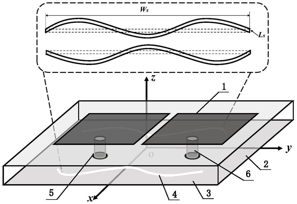
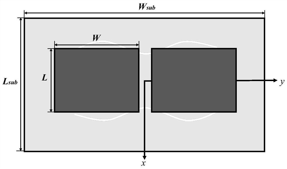
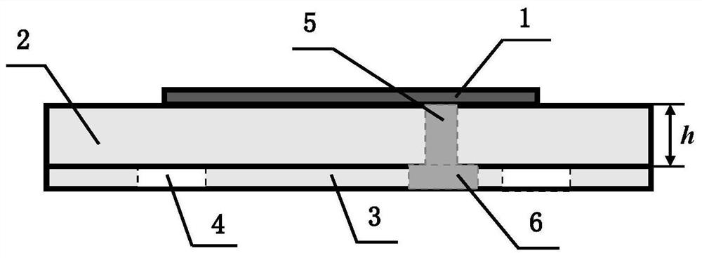
[0049] Such as figure 1 , figure 2 , image 3 with Figure 4 As shown, a curved slot decoupling structure 4 for multiple-input multiple-output array antenna, the working frequency band of MIMO array antenna is 5.725GHz-5.825GHz, the feeding mode is coaxial feeding, and the feeding position is L 1 3.7mm, W 1 is 0.065mm. The MIMO array antenna structure includes: two rectangular microstrip patches 1 on the upper layer, FR4 dielectric substrate 2 on the middle layer, ground plate 3 on the lower layer, two curved slot decoupling structures 4 and two coaxial feed ports 5. One end of the coaxial feed port 5 is connected to the rectangular microstrip patch 1 through the conductor material 6, and the other end is connected to the ground plate. The excitation voltage is fed through the coaxial feed port 5, and then through the conductor material 6 and the FR4 dielectric substrate 2 , two rectangular microstrip patches 1 and a ground plate 3 radiate electromagnetic waves of a spec...

Embodiment 2

[0052] For Embodiment 1 of the present invention, the design method for the shape optimization of the curved groove decoupling structure includes the following steps:

[0053] 1) Design the basic dimensions (length, width) and position of the linear slot decoupling structure, the specific method is as follows: Figure 5 Shown is a two-dimensional schematic diagram of a linear slot decoupling structure for a multiple-input multiple-output array antenna, and the length of the linear slot in the positive direction of the x-axis is L s 24mm, thickness W s 0.5mm, position X s 6mm, Y s -12mm, due to the y-axis symmetrical design, the basic size and position of the two linear slots can be obtained, and the basic radiation performance and decoupling performance requirements can be achieved.

[0054] 2) Determine the curve distance function of the curved groove decoupling structure, and discretize and extract the curve shape parameters. The specific method is: fix the basic size and...


PUM


Abstract

The invention belongs to the field of wireless communication antennas, and relates to a curve groove decoupling structure shape optimization design method of an array antenna. By adopting the method provided by the invention, the array antenna containing the curve slot decoupling structure has good decoupling performance while meeting the design requirement of a specific frequency band. The curve groove decoupling structure is simple in overall structure and small in size, and the structural form of the curve groove decoupling structure is achieved by establishing a design method for optimizing the shape of the curve groove decoupling structure. A curve shape parameter for determining the structural form is obtained by dispersing an implicit distance function between the curve and a straight line of the corresponding linear groove decoupling structure through a multi-order trigonometric function. The design method is wide in design range and high in applicability, the mutual coupling effect of the array antenna is reduced by designing curve shape parameters of the curve grooves, the isolation degree between array elements of the array antenna is greatly improved, and therefore the decoupling performance of the array antenna is achieved.

Description

technical field [0001] The invention belongs to the field of wireless communication antennas, and relates to a shape optimization design method for a curved slot decoupling structure of an array antenna. Background technique [0002] With the rapid development of wireless communication systems, more and more new technologies have the characteristics of large capacity, high transmission rate and strong reliability. Among the many new technologies, the multiple-input multiple-output (MIMO) technology is undoubtedly one of the most potential wireless communication technologies in the field of mobile communication at present, and it has unique advantages in improving channel capacity and data transmission rate. The MIMO array antenna has multiple ports at the receiving end and the transmitting end to transmit at the same time, and it needs to process the complex information flow of multiple channels at the same time, which often makes the array antenna system too large to meet t...

Claims


Application Information

Patent Timeline
Patent Type & Authority Applications(China)
IPC IPC(8): G06F30/20H01Q21/00
CPCG06F30/20H01Q21/00
Inventor 高仁璟汤易邓舒文刘书田
Owner DALIAN UNIV OF TECH
Why Eureka
Try Eureka