Low-cost cooperative treatment and ultra-clean emission process of steel mill sintering flue gas and system thereof

A technology for sintering flue gas and co-processing, applied in the treatment of discharged materials, waste heat treatment, improvement of process efficiency, etc., can solve the problems of low power generation efficiency, no way of removing CO and dioxin, environmental pollution, etc. The effect of improving power generation efficiency, realizing full utilization of waste heat and improving economic benefits

Pending Publication Date: 2021-06-11
彭思尧
View PDF5 Cites 0 Cited by
  • Summary
  • Abstract
  • Description
  • Claims
  • Application Information

AI Technical Summary

Problems solved by technology

The heated air goes to the waste heat boiler to recover heat, and produces low-level energy steam to generate electricity. The power generation efficiency here is very low
[0005] At the same time, the inventors found that in the prior art, the sintering flue gas of the steel plant contained a large amount of CO and dioxins, which polluted the environment. There is no effective way to remove oxins

Method used


Image

  • Low-cost cooperative treatment and ultra-clean emission process of steel mill sintering flue gas and system thereof

Examples


Embodiment 1

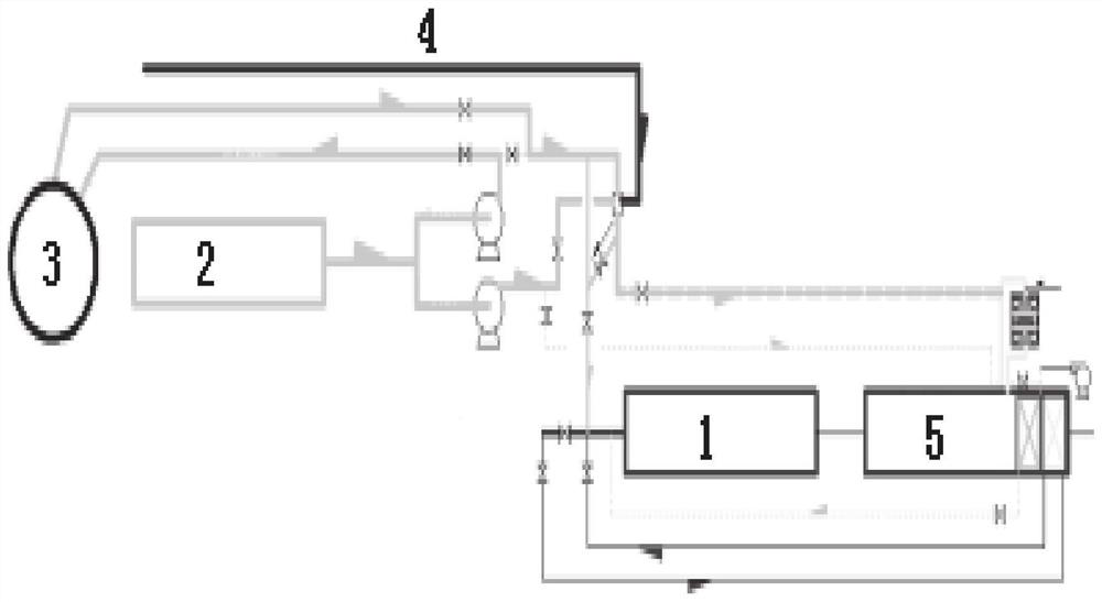
[0054] Such as figure 1 As shown, this embodiment provides a steel plant sintering flue gas waste heat utilization and purification system, including a reaction furnace (1), a sintering machine (2), an annular cooler (3) and a raw material compensation unit (4);

[0055] The reaction furnace (1) mixes the flue gas after heat exchange in the annular cooler (2) with the fuel in the raw material compensation unit (4), and the annular cooler (3) includes a sinter cooling unit and a flue gas heating unit, the flue gas sintered from the sintering machine (2) enters the reaction furnace (1) through the flue gas heating unit;

[0056] The sintering machine (2) includes a sinter outlet and a flue gas outlet, and the flue gas outlet of the sintering machine (2) is connected to the flue gas heating unit of the ring cooler (3); the sinter of the sintering machine (2) is sent into the ring cooling machine (3) in the sinter cooling unit.

Embodiment 2

[0058] This embodiment provides a process for utilization and purification of sintering flue gas waste heat in steel mills. The process is carried out in the steel mill sintering flue gas waste heat utilization and purification system described in Embodiment 1, including the following steps:

[0059] The sintering flue gas in the sintering machine (2) enters the ring cooler (3) for heat exchange, the sintering flue gas heats up, and then enters the reaction furnace (1), where it is co-combusted with the supplemented fuel in the reaction furnace (1) to remove Carbon monoxide and dioxins in the flue gas, the purified flue gas is used to make steam.

[0060] A part of the sintering flue gas enters the annular cooler (3) for heat exchange, and the other part directly enters the reaction furnace (1) for co-combustion with supplementary fuel, and the sintering flue gas entering the annular cooler is 50% of the total amount of sintering flue gas. %, the temperature in the reaction fu...

Embodiment 3

[0064] This embodiment provides a process for utilization and purification of sintering flue gas waste heat in steel mills. The process is carried out in the steel mill sintering flue gas waste heat utilization and purification system described in Example 1, including the following steps: This embodiment provides a The process for utilization and purification of waste heat of sintering flue gas in steel mills is carried out in the waste heat utilization and purification system of sintering flue gas in steel mills described in Example 1, including the following steps:

[0065] The sintering flue gas in the sintering machine (2) enters the ring cooler (3) for heat exchange, the sintering flue gas heats up, and then enters the reaction furnace (1), where it is co-combusted with the supplemented fuel in the reaction furnace (1) to remove Carbon monoxide and dioxins in the flue gas, the purified flue gas is used to make steam.

[0066] A part of the sintering flue gas enters the an...


PUM


Abstract

The invention provides a low-cost cooperative treatment and ultra-clean emission process of steel mill sintering flue gas and a system thereof, and particularly relates to the technical field of waste heat utilization and purification treatment of flue gas. The process comprises the following steps: enabling sintering flue gas in a sintering machine to enter an annular cooler for exchanging heat, heating the sintering flue gas, then enabling the sintering flue gas to enter a reaction furnace for carrying out cooperative combustion with fuel supplemented in the reaction furnace, removing carbon monoxide and dioxin in the flue gas, and preparing the purified flue gas into steam. The problems that a large amount of CO and dioxin are contained in the sintering flue gas of the steel mill in the prior art, the pollution is brought to the environment, desulfurization and denitrification are only concerned generally in the prior art, and the method for effectively removing CO and dioxin in the sintering flue gas of the steel mill is not provided in the prior art are solved.

Description

technical field [0001] The invention relates to the technical field of flue gas waste heat utilization and purification treatment, and specifically provides a low-cost collaborative processing ultra-clean emission process and system for sintering flue gas in a steel plant. Background technique [0002] The information disclosed in this background section is only intended to increase the understanding of the general background of the present invention, and is not necessarily taken as an acknowledgment or any form of suggestion that the information constitutes the prior art already known to those skilled in the art. [0003] The ring cooler is a necessary equipment for cooling sinter, and its function is to cool the high-temperature sinter coming out of the sintering machine. A ring cooling fan is installed at the lower part of the ring cooler, and the ring cooling fan blows air into the ring cooler, and the air passes through the heat exchanger to remove the sensible heat of ...

Claims


Application Information

Patent Timeline
Patent Type & Authority Applications(China)
IPC IPC(8): F27D15/02F27D17/00F22B1/18
CPCF27D15/02F27D17/004F27D17/008F22B1/1892F27D2017/006Y02P10/25
Inventor 彭思尧彭禹舜
Owner 彭思尧
Why Eureka
Try Eureka