Reforming hydrogen production and catalytic combustion integrated device with variable catalyst particle arrangement

A catalyst particle and catalytic combustion technology, applied in the direction of combustion type, combustion method, hydrogen, etc., can solve the problems that the fuel utilization rate cannot reach 100%, the catalyst filling form is single, and the integration of the reformer is low, so as to improve the energy utilization rate , compact structure, enhanced contact effect

Active Publication Date: 2021-06-15
HARBIN INST OF TECH
View PDF16 Cites 1 Cited by
  • Summary
  • Abstract
  • Description
  • Claims
  • Application Information

AI Technical Summary

Problems solved by technology

[0004] Typical hydrocarbon reforming reaction hydrogen production can be divided into three types: steam reforming, partial oxidation reforming and autothermal reforming, among which steam reforming hydrogen production can obtain higher purity hydrogen, and can be Inhibiting the occurrence of coking phenomenon to a certain extent is a research hotspot at present, but this reaction is an endothermic reaction and requires an external heat source
[0005] In addition to the problem of hydrogen supply, although fuel cells are clean and environmentally friendly, the utilization rate of fuel cannot reach 100% at present, so some hydrogen with high calorific value will be wasted
[0006] Although there is a lot of research work on the reformer, most of the reactor modules are separated, and the filling form of the catalyst is also single, which results in a low integration of the reformer, a large system volume, and a low conversion rate. , serious heat loss and a series of problems

Method used


Image

  • Reforming hydrogen production and catalytic combustion integrated device with variable catalyst particle arrangement
  • Reforming hydrogen production and catalytic combustion integrated device with variable catalyst particle arrangement
  • Reforming hydrogen production and catalytic combustion integrated device with variable catalyst particle arrangement

Examples


specific Embodiment approach 1

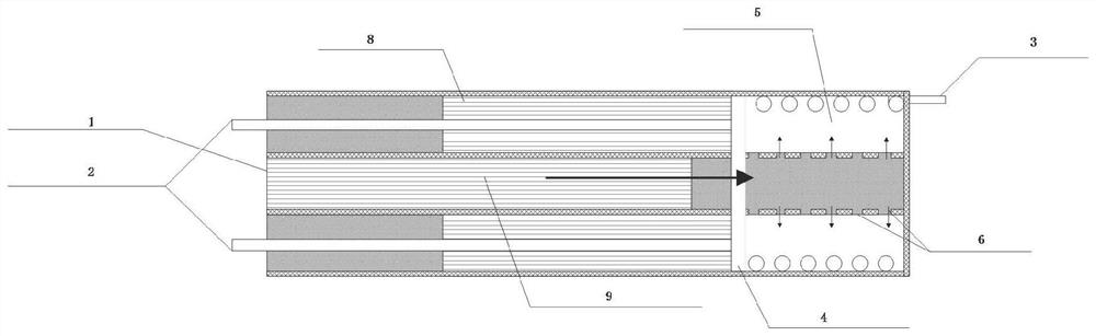
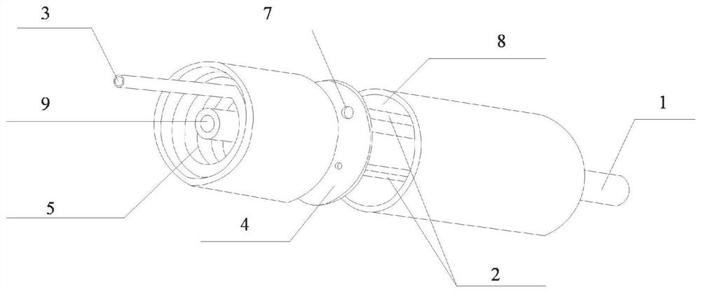
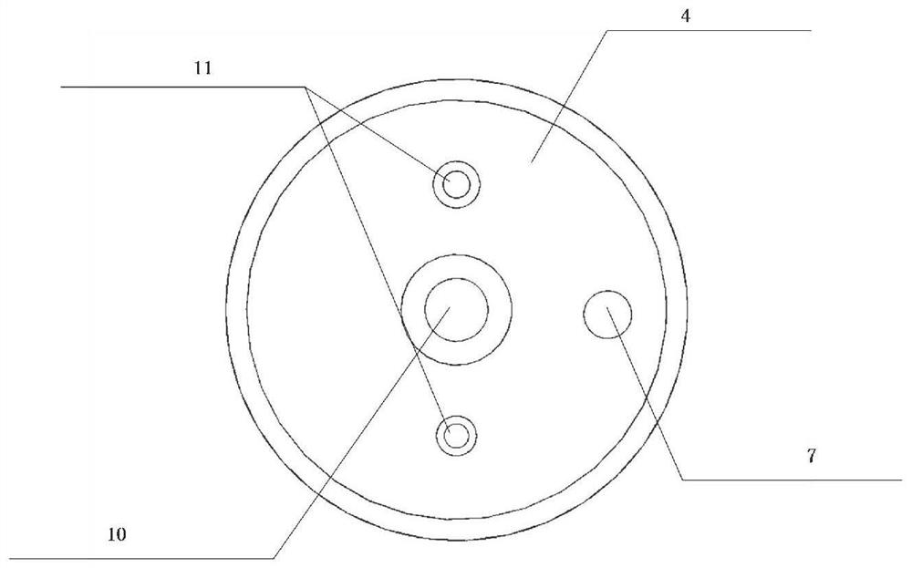
[0031] Specific implementation mode one: see Figure 1-5 This embodiment will be described. The reforming hydrogen production and catalytic combustion integrated device with variable catalyst particle arrangement described in this embodiment, the device is in the form of a sleeve, and catalytic combustion and catalytic reforming reactions occur simultaneously, including catalytic combustion gas inlet 1, catalytic combustion exhaust gas Outlet pipe 2, reformed gas inlet 3, preheating chamber 5, tail gas micropore 6, reformed gas connecting hole 7, reforming chamber 8 and catalytic combustion chamber 9, the catalytic combustion chamber 9 runs through the reforming chamber 8 and the preheating chamber hot chamber 5,

[0032] One end of the catalytic combustion chamber 9 is provided with a catalytic combustion gas inlet 1, and the tail gas of the catalytic combustion enters the catalytic combustion chamber 9 from the catalytic combustion gas inlet 1. At the end of the catalytic c...


PUM


Abstract

The invention discloses a reforming hydrogen production and catalytic combustion integrated device with variable catalyst particle arrangement. The appearance of the device is in a sleeve form, catalytic combustion and catalytic reforming reaction are carried out at the same time, the device is divided into a catalytic combustion cavity, a preheating cavity and a reforming cavity, catalytic combustion tail gas enters the catalytic combustion cavity from an inlet, a large number of micropores are formed in the tail end of the sleeve, reacted tail gas enters the preheating cavity through the micropores to preheat a reformer and then is discharged out of the device through an outlet pipe. On the other end , reforming fuel enters from the inlet, flows in the spiral pipe, is preheated by catalytic combustion tail gas and then enters the reforming cavity. The device integrates tail gas catalytic combustion, preheating and reforming hydrogen production, the tail gas is subjected to catalytic combustion, heat is provided for reforming reaction, meanwhile, fuel preheating is integrated, the whole system is compact in structure, and the conversion rate is further improved.

Description

technical field [0001] The invention relates to a reforming hydrogen production and catalytic combustion integrated device with variable catalyst particle arrangement, belonging to the technical field of fuel reforming and catalytic combustion. Background technique [0002] A fuel cell is a chemical device that directly converts the chemical energy of fuel into electrical energy, also known as an electrochemical generator. It has great advantages such as high energy conversion efficiency and low noise. Common types of fuel cells include alkaline fuel cells, proton exchange membrane fuel cells, molten carbonate fuel cells, solid oxide fuel cells, and the like. Among them, the proton exchange membrane fuel cell not only has a low operating temperature, can be quickly started, but also has a large specific power and specific energy density, which is a very advantageous fuel cell. [0003] Fuel cells require a reliable hydrogen supply system. The traditional hydrogen supply m...

Claims


Application Information

Patent Timeline
Patent Type & Authority Applications(China)
IPC IPC(8): C01B3/38C01B3/40F23G7/07H01M8/04014H01M8/0612
CPCC01B3/38C01B3/40F23G7/07H01M8/0618H01M8/04014C01B2203/0233C01B2203/1011C01B2203/1017Y02P20/52Y02E60/50
Inventor 秦江哈婵王聪程昆林
Owner HARBIN INST OF TECH
Why Eureka
Try Eureka