Fin type SCR catalyst attachment skeleton structure and flue gas denitration system and method thereof

A technology of SCR catalyst and skeleton structure, which is applied in the field of low-temperature SCR denitrification, can solve the problems of high catalyst cost, failure to meet operating requirements, and activity failure, etc., and achieve wide-load denitrification, improve anti-poisoning ability, and weaken the impact of poisoning Effect

Active Publication Date: 2021-06-18
山西清泽阳光环保科技有限公司
View PDF5 Cites 0 Cited by
  • Summary
  • Abstract
  • Description
  • Claims
  • Application Information

AI Technical Summary

Problems solved by technology

In addition, when the tail flue gas temperature is high (>290°C), the ammonia bisulfate poisoning of the catalyst will also be reduced, but the flue gas temperature in low-load thermal power plants or non-power industries such as steel and glass is not high. does not meet the operating requirements, and at low temperatures, SO 2 Extremely easy with NH 3 combined with subsequent further oxidation to generate ammonium bisulfate ((NH 4 )HSO 4 )
[0007] At present, the research focus of my country's scientific research institutes and universities is biased towards catalyst formulation development, reaction mechanism, catalyst poisoning and regeneration, etc. There are few studies on the molding and preparation process of monolithic catalysts, mainly relying on foreign technology Therefore, it is necessary to develop a new type of SCR denitrification catalyst skeleton mechanism and denitrification system and method to solve the problem of SCR catalyst activity failure and low temperature poisoning in the process of low temperature flue gas denitrification problems, and overcome the disadvantages of easy ash deposition at low flue gas flow rates (<3m / s)

Method used


Image

  • Fin type SCR catalyst attachment skeleton structure and flue gas denitration system and method thereof
  • Fin type SCR catalyst attachment skeleton structure and flue gas denitration system and method thereof
  • Fin type SCR catalyst attachment skeleton structure and flue gas denitration system and method thereof

Examples


Embodiment Construction

[0052] In order to make the object, technical solution and advantages of the present invention clearer, the present invention will be further described in detail below in conjunction with the accompanying drawings and embodiments. It should be understood that the specific embodiments described here are only used to explain the present invention, not to limit the present invention.

[0053] Based on the embodiments of the present invention, all other embodiments obtained by persons of ordinary skill in the art without creative efforts fall within the protection scope of the present invention.

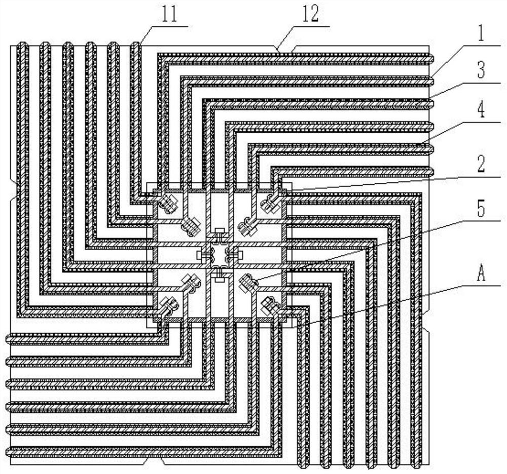
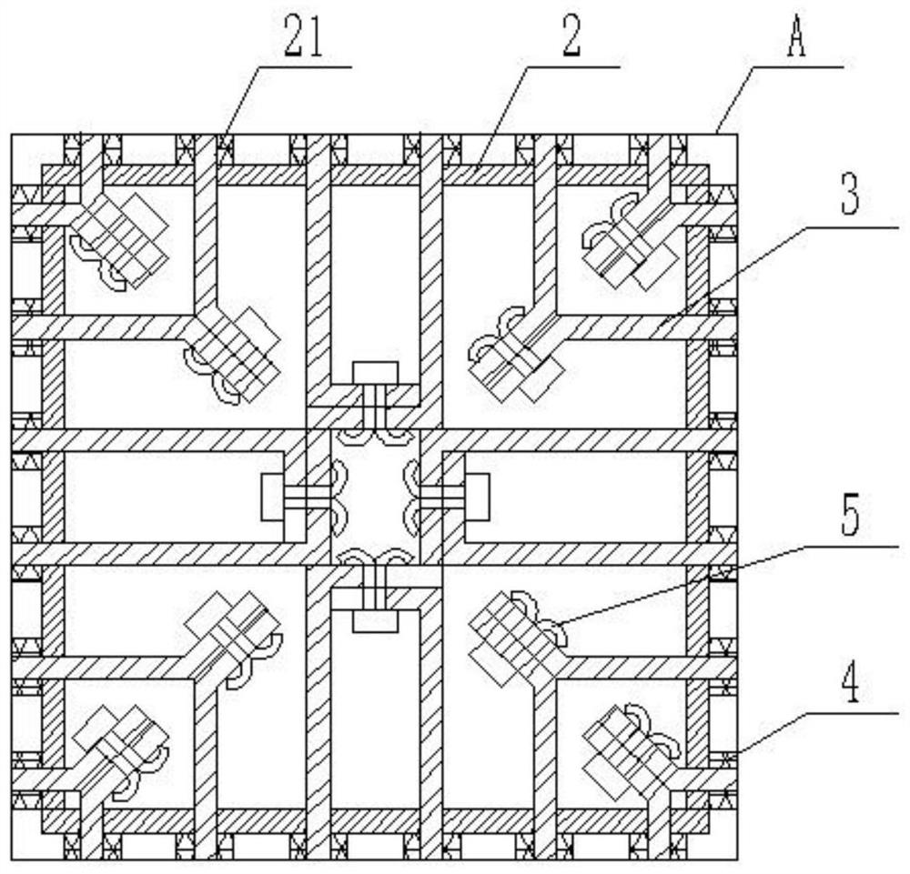
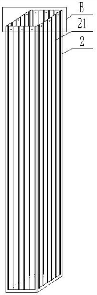
[0054] see figure 1 , is a structural schematic diagram of a finned SCR catalyst attachment skeleton structure provided by an embodiment of the present invention. The finned SCR catalyst attachment skeleton structure includes: an outer box body, an inner box body 2 and a plurality of finned skeletons 3 .

[0055] see figure 1 with Figure 9 to Figure 10 , the outer box 1 is in the sh...


PUM


Abstract

The invention provides a fin type SCR catalyst attachment skeleton structure and a flue gas denitration system and a method thereof, and belongs to the technical field of low-temperature SCR denitration, the skeleton structure comprises: an outer box body, wherein each side wall of which is provided with a plurality of trapezoidal grooves formed by outward extrusion; an inner box body arranged in the outer box body, wherein each side wall of the inner box body is provided with a plurality of insertion grooves with openings in one ends; fin skeletons, wherein one end of each fin skeleton is inserted into the corresponding trapezoidal groove, the other end of each fin skeleton is inserted into the corresponding insertion groove, and the end parts of every two fin skeletons are fixedly connected through a pin; and two side walls of each fin skeletonare coated with an SCR catalyst; a plurality of baffle plates arranged at one end of the inner box body and used for fixing a plurality of fin skeletons. According to the system and the method, the normal-temperature air can be heated by using the molten salt solar condensation-heat storage system to overcome deactivation or poisoning of the SCR catalyst, and the flow speed of flue gas in the flue can be increased by increasing the flow speed of the high-temperature air.

Description

technical field [0001] The invention relates to the technical field of low-temperature SCR denitrification, in particular to a finned SCR catalyst attachment skeleton structure and a flue gas denitrification system and method. Background technique [0002] Selective Catalytic Reduction (SCR for short), as a mainstream technology widely used in thermal power plant flue gas denitrification at home and abroad, has very mature technical experience and high denitrification efficiency. The tail gas temperature of non-electric industries such as steel, glass, cement, and coking plants is also low. The industrial application of low-temperature SCR technology has become a current bottleneck. [0003] At present, the main technical difficulties of low-temperature SCR denitrification technology are as follows: one is the most widely used V 2 o 5 -WO 3 (MoO 3 ) / TiO 2 The catalyst activity temperature is 300°C-400°C, while the temperature of the existing sintering flue gas, coke ove...

Claims


Application Information

Patent Timeline
Patent Type & Authority Applications(China)
IPC IPC(8): B01D53/88B01D53/90B01D53/56B01D53/60
CPCB01D53/88B01D53/90B01D53/8628B01D53/8631B01D53/8637B01D2255/20723B01D2255/20776B01D2255/20707B01D2255/20769B01D2255/90B01D2251/2062B01D2258/0283
Inventor 张学清李晓靖施天哲原雷鹏杨江玲曹嘉郝婷娟刘斌樊晓文
Owner 山西清泽阳光环保科技有限公司
Why Eureka
Try Eureka