Supercharge Your Innovation With Domain-Expert AI Agents!

Battery runner sealing structure and application thereof

A sealing structure and flow channel technology, applied in the field of energy storage, can solve the problems of liquid leakage, resistance drop and leakage current, etc., and achieve the effect of increasing contact area, saving output consumption, and long-term stable operation

Inactive Publication Date: 2021-06-18
坤厚储能科技有限公司
View PDF8 Cites 0 Cited by
  • Summary
  • Abstract
  • Description
  • Claims
  • Application Information

AI Technical Summary

Problems solved by technology

When the required liquid pressure is relatively large, there is a risk of liquid leakage due to the single-sided sealing of the structure
In addition, the traditional flow channel is designed as a straight channel, and it is not easy to meet the requirements of resistance drop and leakage current during design.

Method used


Image

  • Battery runner sealing structure and application thereof
  • Battery runner sealing structure and application thereof
  • Battery runner sealing structure and application thereof

Examples


Embodiment 1

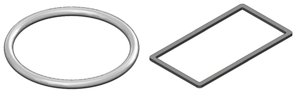
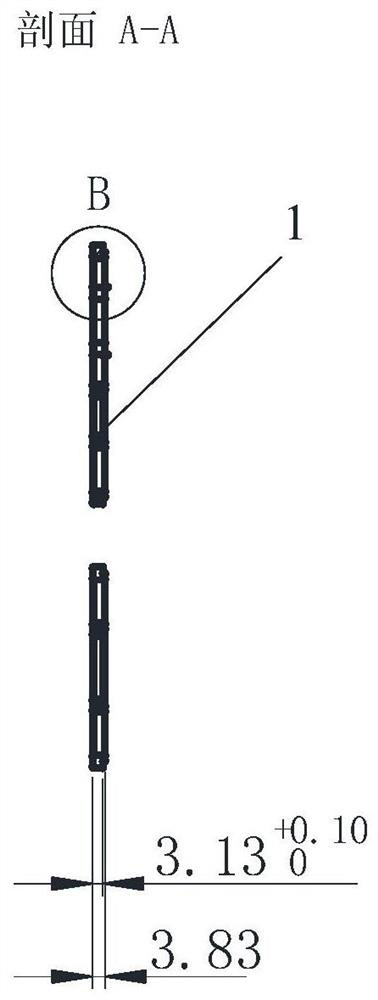
[0043] This embodiment proposes a battery flow channel sealing structure, which is to open a flow channel on the battery plate frame and seal it; a unit battery is surrounded by an upper plate frame 2 and a lower plate frame 3 that are buckled together (see Figure 7 and Figure 8 ), a serpentine flow channel 4 is provided on the lower plate frame, and the serpentine flow channel 4 is sealed by a "7"-shaped sealing ring 1, see figure 2 , image 3 and Figure 4 : the cross section of the sealing ring is a right angle "7", the top of the "7" is in contact with one side of the upper frame, and the bottom of the "7" is in contact with the side of the lower frame where the flow channel is opened.

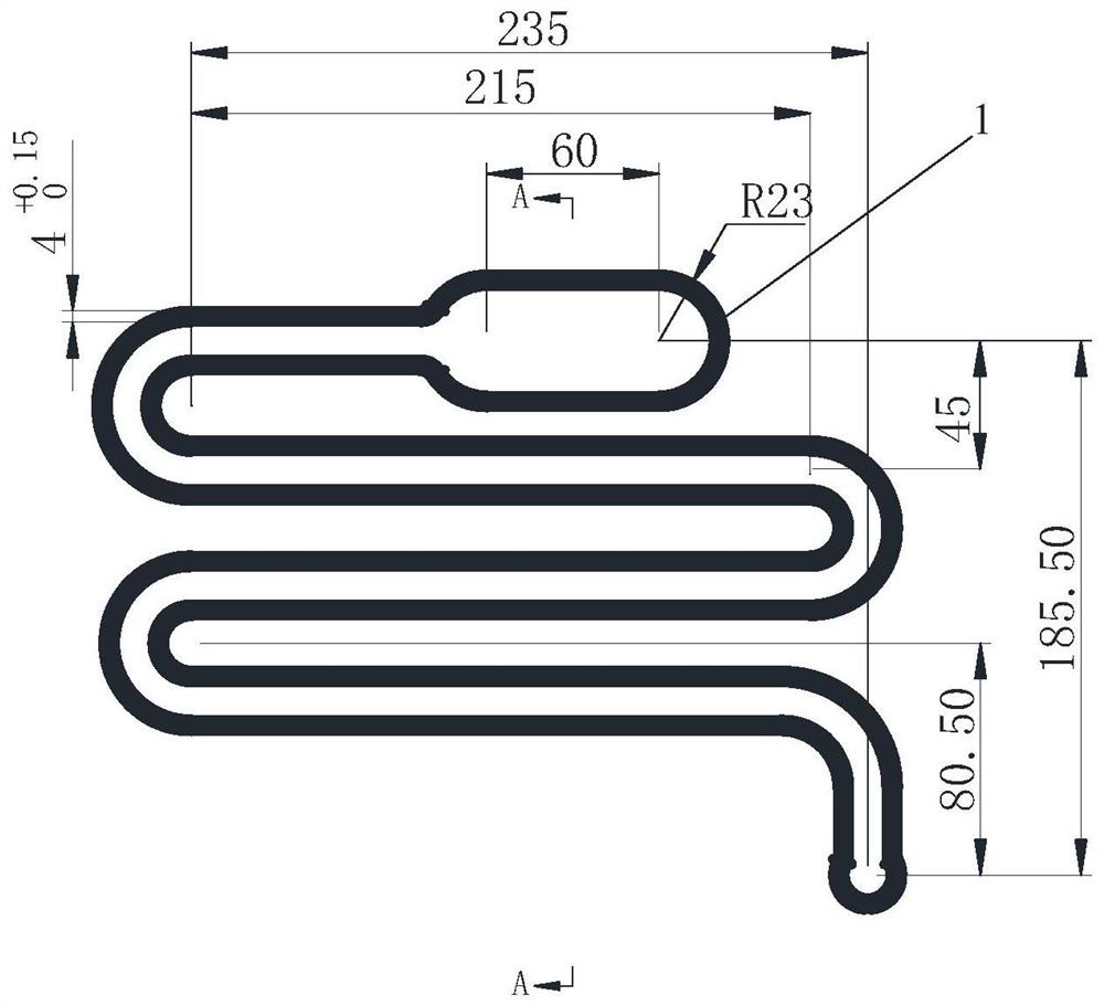
[0044] see Figure 6 , the serpentine flow channel 4 includes an oblong liquid inlet 5, and one end of the long axis of the liquid inlet 5 is connected to the serpentine flow channel 4 bent back and forth, and the bent part is arc-shaped; the back and forth bend The folded channel h...

Embodiment 2

[0073] This embodiment proposes a battery flow channel sealing structure, which is to open a flow channel on the battery plate frame and seal it; a unit battery is surrounded by an upper plate frame 2 and a lower plate frame 3 that are buckled together. A serpentine flow channel 4 is provided on the plate frame, and the serpentine flow channel 4 is sealed by a "7"-shaped sealing ring 1: the cross section of the sealing ring is a right-angled "7" shape, and the top of the "7" shape is in line with the One side of the upper frame is in contact, and the bottom of the "7" shape is in contact with the side of the lower frame on which the flow channel is opened.

[0074] The serpentine flow channel includes an elliptical shared flow channel (multiple unit cells are assembled, the liquid inlet 5 and the shared flow channel are at the same position), and one end of the long axis of the ellipse is connected to the flow channel bent back and forth, The bent portion is arc-shaped; the sa...


PUM

PropertyMeasurementUnit
Bump heightaaaaaaaaaa
Overall widthaaaaaaaaaa
Thicknessaaaaaaaaaa

Abstract

The invention provides a battery runner sealing structure and application thereof. According to the battery runner sealing structure, a flow channel is formed in a battery panel frame and is sealed; one unit battery is enclosed by an upper plate frame and a lower plate frame which are buckled together, a snakelike runner is arranged on the lower plate frame, the snakelike runner is sealed by a sealing ring, the cross section of the sealing ring is right-angled 7-shaped, the top of the 7-shaped structure is contacted with one surface of the upper plate frame, and the bottom of the 7-shaped structure is contacted with one surface, provided with the runner, of the lower plate frame. Aiming at the characteristics that the iron-chromium flow battery is large in capacity and the electrolyte is acidic, the invention designs a sealing ring with a novel structure, and the sealing ring is used for sealing a runner and a carbon plate. According to the sealing structure, the contact area of the sealing ring and a part is increased, and good sealing can be kept in the operation process; the sealing ring is made of the ethylene-propylene-diene monomer material, can be used in acid liquid without corrosion, and can effectively prevent liquid leakage.

Description

technical field [0001] The invention belongs to the technical field of energy storage, and in particular relates to a battery sealing structure. Background technique [0002] Redox flow battery is a secondary battery with liquid electrolyte as the electrode active material. According to the different redox pairs, it can be divided into all-vanadium flow battery, zinc-bromine flow battery, sodium polysulfide / bromine flow battery , zinc / nickel flow battery, iron / chromium flow battery, vanadium / polyhalide flow battery, zinc / cerium flow battery, etc. The structural materials of the redox flow battery are mostly carbon materials, engineering plastics, etc., and the price is low; the battery can achieve a large capacity and is safe and guaranteed; because the power and capacity of the battery are designed independently of each other, the charging and discharging and mediation capacity are independent. Very flexible. Among them, the iron-chromium flow battery uses Fe 2 + / Fe 3...

Claims


Application Information

Patent Timeline
IPC IPC(8): H01M8/0263H01M8/0273H01M8/0276H01M8/0282H01M8/18
CPCH01M8/0263H01M8/0273H01M8/0276H01M8/0282H01M8/188Y02E60/50
Inventor 不公告发明人
Owner 坤厚储能科技有限公司
Features
  • R&D
  • Intellectual Property
  • Life Sciences
  • Materials
  • Tech Scout
  • Unparalleled Data Quality
  • Higher Quality Content
  • 60% Fewer Hallucinations
Learn More