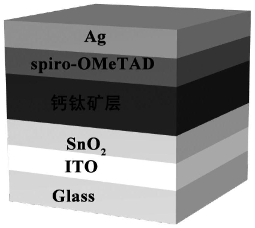
Preparation method of perovskite solar cell with perovskite layer passivated by nanofibers
A technology of solar cells and nanofibers, applied in circuits, photovoltaic power generation, electrical components, etc., can solve the problems of low efficiency and poor stability of perovskite cells, and achieve improved photoelectric conversion efficiency, improved performance, and controllable dimensions Effect
- Summary
- Abstract
- Description
- Claims
- Application Information
AI Technical Summary
Problems solved by technology
Method used
Image

Examples
Embodiment 1
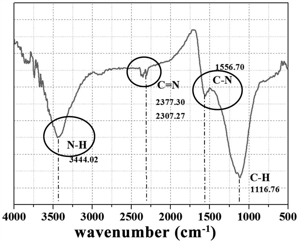
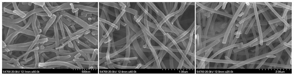
[0023] First, the nanofibers are processed into polymer nanofibers by electrospinning technology from a polyacrylonitrile / N,N-dimethylformamide solution with a mass fraction of 10 wt%. The electrospinning parameters are as follows: ①Nozzle and negative high voltage generator connection, the negative high voltage value is -5kV; ②The distance between the nozzle and the receiving plate is 15cm; ③The receiving plate is connected to the positive high voltage generator, and the positive high voltage is +10kV; ④The feeding speed is controlled by the propulsion pump, and the feeding speed is 1.0 mL·h -1 , to obtain polymer nanofibers. Then, the polymer nanofibers were kept at 240° C. for 60 minutes in an air atmosphere, then passed through nitrogen, and then heated to 800° C., kept for 60 minutes in a nitrogen atmosphere, and then cooled to obtain nanofibers. The heating and cooling rates are both 5°C per minute.
[0024] Next: (1) Conductive glass (fluorine-doped SnO 2 Conductive ...
PUM
| Property | Measurement | Unit |
|---|---|---|
| Diameter | aaaaa | aaaaa |
| Thickness | aaaaa | aaaaa |
Abstract
Description
Claims
Application Information