Multi-port grid-shaped modularized multi-level direct-current converter

A DC converter, multi-level technology, applied in the direction of converting DC power input to DC power output, adjusting electrical variables, output power conversion devices, etc., can solve the problem of uneven stress distribution of switching devices, uneven device stress, voltage Inability to control independently and other problems to achieve the effect of standardized production and assembly, flexible expansion of the number of ports and power capacity

Active Publication Date: 2021-06-25
XIDIAN UNIV
View PDF6 Cites 1 Cited by
  • Summary
  • Abstract
  • Description
  • Claims
  • Application Information

AI Technical Summary

Problems solved by technology

The disadvantage of the common bus type MPC is that the circuits are independent of each other, resulting in a large number of devices used, low utilization rate, and uneven stress distribution of switching devices; device multiplexing MPC still does not solve the uneven distribution of device voltage and current stress and the stress of some devices is too high The problem
In the switched capacitor MPC network, the capacitor voltages at all levels cannot be independently controlled, and the charging and discharging process between the capacitors is directly connected in parallel, which will generate large current spikes and device losses
[0004] Due to the limitation of device stress and topological structure, the non-isolated MPC in the existing technology cannot meet the rapid development needs of the number of ports, voltage level, and power capacity of medium and low voltage DC systems such as distributed new energy power generation to a certain extent, and cannot be formed. Efficient, flexible and expandable modular topology and control method

Method used


Image

  • Multi-port grid-shaped modularized multi-level direct-current converter
  • Multi-port grid-shaped modularized multi-level direct-current converter
  • Multi-port grid-shaped modularized multi-level direct-current converter

Examples


Embodiment 1

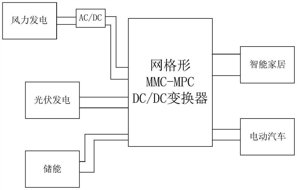
[0023] The application scenarios of a multi-port grid-shaped modular multi-level DC converter provided by the present invention are as follows: figure 1 As shown, it can be new energy fields, household appliances and so on. Application scenarios such as: wind power generation, photovoltaic power generation, smart home, electric vehicles, etc.

[0024] It can be understood that the current new energy business continues to develop. Wind power and photovoltaic power generation are renewable new energy sources. However, new energy power generation has intermittent and fluctuating shortcomings. Using the charging and discharging characteristics of energy storage devices such as batteries can play a role in new energy power generation. The function of peak shaving and valley filling enables the system to output reliable and stable power as a whole and improves power quality. In today's household appliances and IT products, most of them work in the DC state, such as DC inverter air ...

Embodiment 2

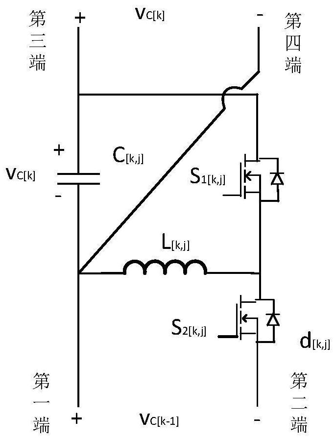
[0029] In one embodiment, the Buck-Boost module in the present invention includes: a capacitor, an inductor, a first switch tube and a second switch tube, the positive terminal of the capacitor is the third terminal of the Buck-Boost module, and the positive terminal of the capacitor Connected to the first end of the first switch tube, the negative end of the capacitor is the fourth end and the first end of the Buck-Boost module, the negative end of the capacitor is connected to one end of the inductor, and the second end of the inductor is connected to the first end of the switch tube The other end of the inductor is connected to the first end of the second switch tube, and the second end of the second switch tube is the second end of the Buck-Boost module.

[0030] Such as image 3 As shown, the Buck-boost circuit contains a capacitor C [k,j] , an inductance L [k,j] and two switching tubes S 1[k,j] ,S 2[k,j] , the capacitance and inductance are respectively connected in ...

Embodiment 3

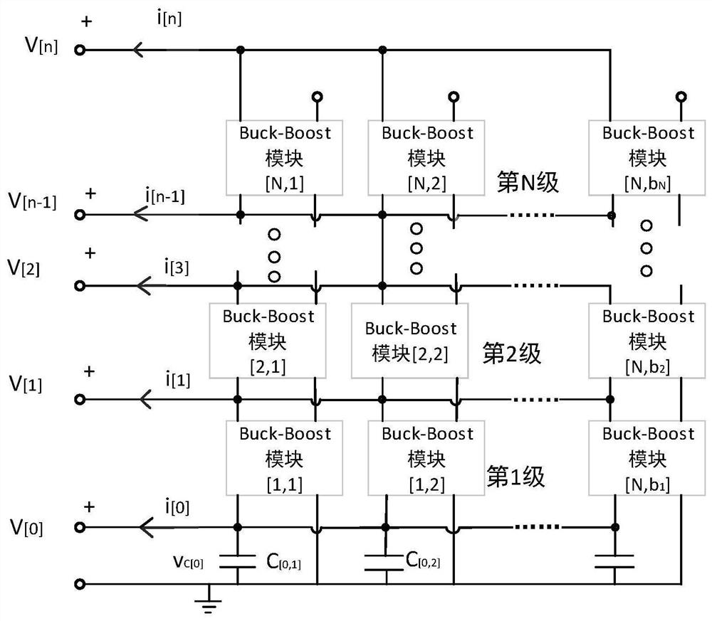
[0033] In one embodiment, the number of stages of the multiple combinational circuits is N, and the number of Buck-Boost modules in each level of multiple combinational circuits is b N , b in the n-1th level combinational circuit i The third terminal of a Buck-Boost module and the bth stage in the nth stage combination circuit i The first ends of the Buck-Boost modules are connected, and the bth in the n-1th level combined circuit i The fourth terminal of a Buck-Boost module and the b-th in the nth-level combined circuit i Connect to the second end of a Buck-Boost module.

[0034] Of course, there may also be a combined circuit with a different number of Buck-Boost modules in each level of combined circuit than in other combined circuits. The number of Buck-Boost modules in this level of combined circuit is related to the current stress distribution relevant.

[0035] In order to facilitate the analysis of the working principle of the converter provided by the present inve...


PUM


Abstract

The invention provides a multi-port grid-shaped modularized multi-level direct-current converter. According to the multi-port grid-shaped modularized multi-level direct-current converter, the connection mode that completely same non-isolated DC-DC converter modules are connected in parallel at the same stage and the output ends of the DC-DC converters at different stages are sequentially connected in series is adopted, and Buck-Boost modules are selected as single DC-DC converter modules; the multi-port converter generally has a relatively strong coupling effect between ports, so that each DC-DC converter further comprises a control loop, so that multi-port decoupling control can be realized. The modules in the converter have identical circuit structures and electrical parameters, standardized production and assembly can be realized, and current sharing and voltage sharing among the modules can be realized. According to the multi-port grid-shaped modularized multi-level direct-current converter topological structure, on the basis of meeting port characteristic requirements and device voltage and current stress balanced distribution, the optimal design of minimum filling of the number of modules in a grid structure is achieved, and flexible expansion of the number of ports, the voltage level and the power capacity can be achieved.

Description

technical field [0001] The invention belongs to the field of power transmission and distribution of electric power systems, and in particular relates to a multi-port grid-shaped modular multi-level DC converter. Background technique [0002] New energy is a sustainable energy source. Distributed new energy power generation is a power generation method different from traditional energy. Although it can be discovered, it has obvious intermittency, and there are many voltage levels and large power fluctuations. It needs medium and low voltage direct current. The network effectively interconnects multiple power sources and loads to achieve optimal energy allocation. The multi-port DC / DC converter (Multiple Port DC / DC Converter, MPC) can quickly realize the power matching between the power supply and the load with different voltages and different internal resistances, effectively reducing the number of converters used in the power grid, and facilitating voltage and power The cen...

Claims


Application Information

Patent Timeline
Patent Type & Authority Applications(China)
IPC IPC(8): H02M3/158
CPCH02M3/1582
Inventor 孙乐嘉弋锦张艺蒙张玉明薛璇
Owner XIDIAN UNIV
Why Eureka
Try Eureka