
Device and method for improving mask electrolytic machining precision through arc-shaped spraying cathode movement

A technology of cathode movement and machining accuracy, applied in the direction of electrodes, etc., can solve the problems of low machining efficiency, difficulty in ensuring machining quality and machining accuracy, and no consideration of the uniformity of the size of the micro-pit array structure, so as to ensure the machining quality and reduce the current edge. effect, the effect of improving the localization of processing

Inactive Publication Date: 2021-06-29
DALIAN UNIV OF TECH
View PDF10 Cites 2 Cited by
  • Summary
  • Abstract
  • Description
  • Claims
  • Application Information

AI Technical Summary

Problems solved by technology

However, this method does not take into account the size uniformity among micropit array structures
And when processing large-area metal microstructures, it is necessary to continuously move the nozzle to realize the processing of each microstructure, resulting in low processing efficiency of this method
[0008] To sum up, the existing methods for improving the accuracy of mask electrolytic machining have certain limitations, and it is difficult to guarantee the processing quality and machining accuracy requirements when mask electrolytic machining of metal microstructures

Method used


Image

  • Device and method for improving mask electrolytic machining precision through arc-shaped spraying cathode movement
  • Device and method for improving mask electrolytic machining precision through arc-shaped spraying cathode movement
  • Device and method for improving mask electrolytic machining precision through arc-shaped spraying cathode movement

Examples


Embodiment Construction

[0038] The present invention is further detailed below with reference to the accompanying drawings and specific embodiments.

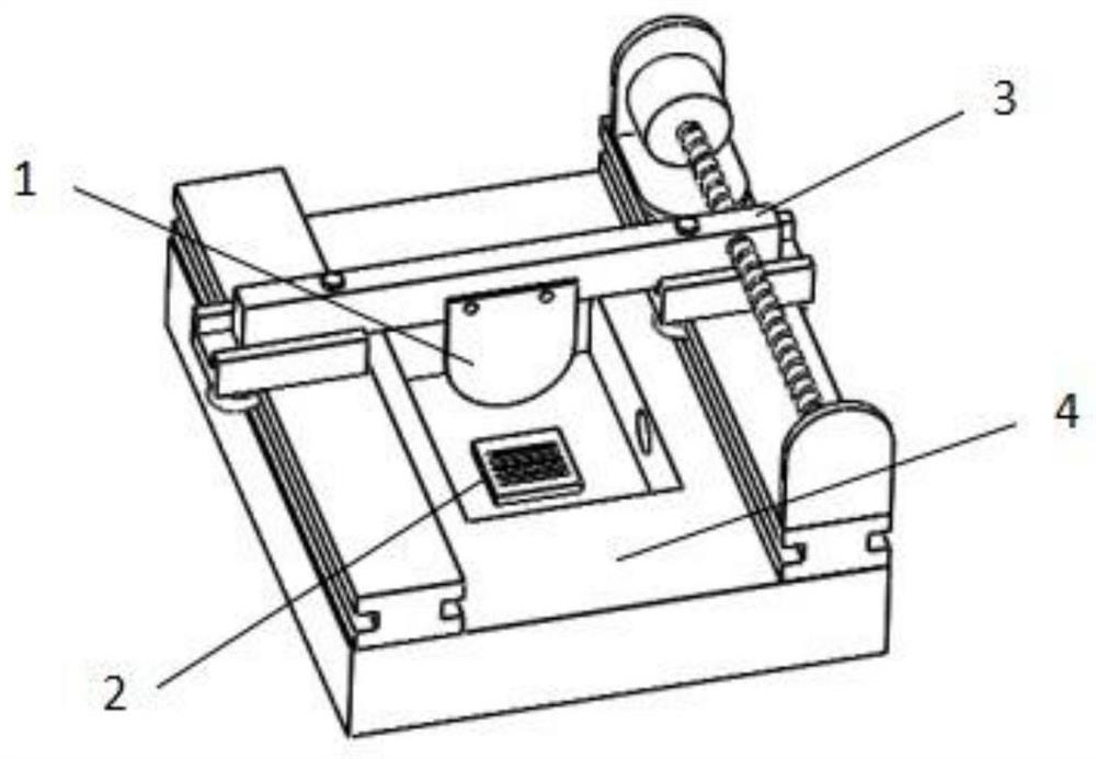
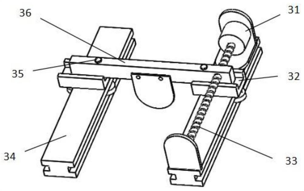
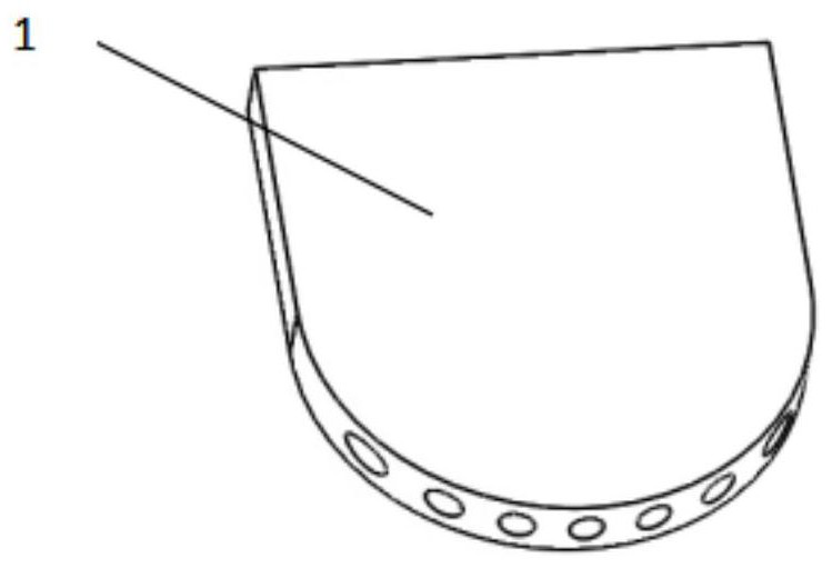
[0039] A curved injection cathode mobile device structure for improving mask electrolysis processing accuracy, such as figure 1 Indicated. This includes: the curved cathode nozzle structure 1, the anode workpiece 2, the moving mechanism 3, the electrolytic cell 4, the anode workpiece 2 is placed at the bottom of the electrolytic cell 4, and the moving mechanism 3 is fixed to the electrolytic cell 4, and the curved cathode nozzle structure 1 is fixed The moving mechanism 3 is above. Mobile mechanism 3 structurefigure 2 As shown, the motor 31 drives the transmission screw 33 to rotate, and the drive screw 33 is driven to fit the moving slider 32 assembled thereto along the guide rail 34 to perform a phase transfer movement. The support beam 36 is connected to the moving slider 32 by tightening the screw 35. Such as image 3 The schematic shown in the curved c...


PUM


Abstract

The invention discloses a device and method for improving mask electrolytic machining precision through arc-shaped spraying cathode movement. The device comprises an arc-shaped cathode nozzle structure, an anode workpiece, an electrolytic bath, a motor, a guide rail, a movable sliding block, a transmission lead screw and a supporting beam. The anode workpiece is arranged at the bottom of the electrolytic bath, is completely immersed in an electrolyte and forms a conductive loop with a cathode nozzle. The motor drives the transmission lead screw to rotate, and the transmission lead screw drives the sliding block and the supporting beam on the sliding block to do reciprocating translational motion along the guide rail. The arc-shaped cathode nozzle structure is fixed on the supporting beam, and a moving mechanism drives the arc-shaped cathode nozzle structure to change in position. In the mask electrolytic machining process, an arc-shaped moving cathode is adopted to achieve the purpose of improving electric field distribution in the machining process, and the etching uniformity of a microstructure is improved. The electrolyte sprayed on the arc-shaped cathode can discharge electrolytic products in the microstructure in time, mass transfer is enhanced, and the localized corrosion removal capacity is improved. The device is simple and easy to operate, the uniformity and locality of the metal microstructure can be effectively improved, and the mask electrolytic machining precision is improved.

Description

Technical field [0001] The present invention belongs to the field of fine electrolyzing processing, and is related to a mask electrolytic processing apparatus and method, and more particularly to an arc-shaped injection cathode mobile device and method for improving the mask electrolytic processing accuracy. Background technique [0002] With the rapid development of micro-nanotechnology, the application of metal microstructure is also expanding. At present, the common processing methods of metal microstructure include laser microfabrication, ultrasonic fine processing, micrulte processing, electric spark processing, and electrolysis processing. Among them, the electrolysis processing has no loss of workpiece surface after processing, and has no residual stress and high production efficiency. The mask electrolysis is made as a kind of electrolysis technology, which has low production cost, and can have a large amount of molding of metal microstructure, with a wide range of applic...

Claims


Application Information

Patent Timeline
Patent Type & Authority Applications(China)
IPC IPC(8): C25D5/02C25D5/08C25D17/12
CPCC25D5/022C25D5/08C25D17/12
Inventor 杜立群关发龙于洋肖海涛王胜羿温义奎翟科白志鹏
Owner DALIAN UNIV OF TECH
Features
  • Generate Ideas
  • Intellectual Property
  • Life Sciences
  • Materials
  • Tech Scout
  • Unparalleled Data Quality
  • Higher Quality Content
  • 60% Fewer Hallucinations
Learn More