Vortex electronic mode identification system, method and device and electronic equipment

A modal recognition and electronic technology, applied in character and pattern recognition, neural learning methods, biometric recognition, etc., can solve the nonlinear distortion of vortex electronic offset, the effect is not ideal, and it cannot resist nonlinear distortion well and other issues, to achieve the effect of high recognition accuracy, low hardware complexity and cost, and reduced impact

Active Publication Date: 2021-07-02
TSINGHUA UNIV
View PDF5 Cites 2 Cited by
  • Summary
  • Abstract
  • Description
  • Claims
  • Application Information

AI Technical Summary

Problems solved by technology

Therefore, the vortex electrons will be affected by the residual magnetic field and will be offset and severely nonlinearly distorted. The effect of OAM mode separation based on the device-based method of ideal magnetic field modeling is not ideal.
In addition, it is also possible to use an image acquisition device, such as a CCD (Charge Coupled Device, Charge Coupled Device) camera to collect the diffraction image of the electronic OAM, and then perform OAM mode recognition and restore information through image recognition, but conventional image recognition methods only It can extract surface features such as the edge of the image, but cannot cope well with the nonlinear distortion caused by the residual magnetic field
Table 1 compares the above-mentioned common vortex electron OAM modal recognition methods, mainly based on device methods and image processing methods. Both methods have their own advantages and disadvantages, but neither of them can better resist vortex electron diffraction. non-linear distortion of the image

Method used


Image

  • Vortex electronic mode identification system, method and device and electronic equipment
  • Vortex electronic mode identification system, method and device and electronic equipment
  • Vortex electronic mode identification system, method and device and electronic equipment

Examples


Embodiment Construction

[0062] Embodiments of the invention are described in detail below, examples of which are illustrated in the accompanying drawings. The embodiments described below by referring to the figures are exemplary and are intended to explain the present invention and should not be construed as limiting the present invention.

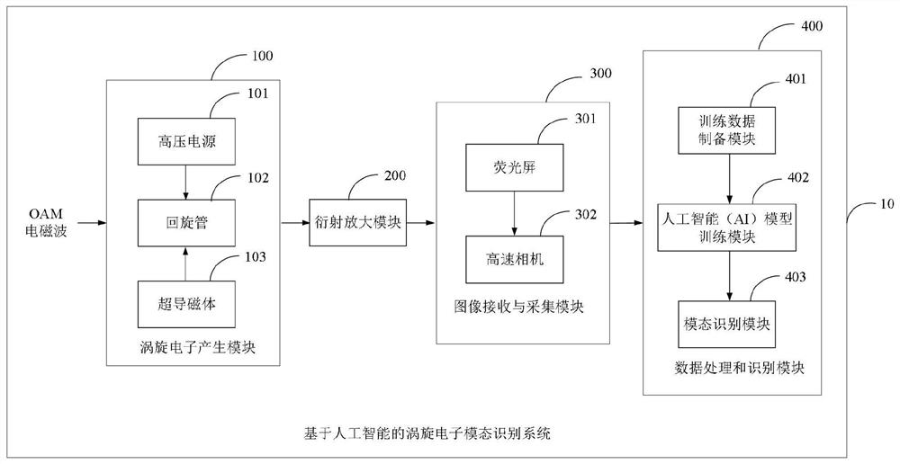
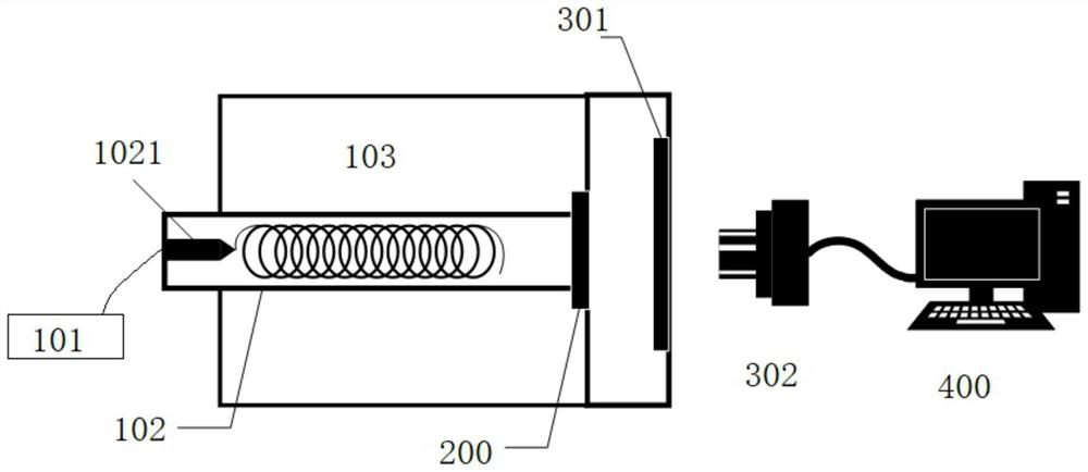
[0063] Such as figure 1 As shown, a vortex electron mode identification system 10 includes a vortex electron generation module 100 , a diffraction amplification module 200 , an image receiving and acquisition module 300 , and a data processing and identification module 400 .

[0064] Wherein, the vortex electron generation module 100 includes a high voltage power supply 101, a gyrotron 102 and a superconducting magnet 103, wherein the gyrotron 102 is mainly composed of a high-speed electron gun 1021 and a cylindrical electron gyrotron generation module. The high-voltage power supply 101 supplies power to the electron gun 1021 and provides the high-voltage direct...


PUM


Abstract

The invention discloses a vortex electron modal identification system, method and device and electronic equipment. The system comprises a vortex electron generation module, a diffraction amplification module, an image receiving and collecting module, a data processing and recognition module, a training data preparation sub-module, an artificial intelligence model training sub-module and a modal identification module. Cyclotron electrons generated by the vortex electron generation module are coupled with the orbital angular momentum to generate vortex electron beams carrying different modes of OAM (orbital angular momentum); the diffraction amplification module diffracts and amplifies the vortex electron beam. The image receiving and collecting module is used for receiving the vortex electron beam subjected to diffraction amplification and collecting an OAM field intensity distribution image; the data processing and identification module receives the OAM field intensity distribution image and carries out OAM modal identification. The system not only realizes vortex electronic orbital angular momentum modal identification, but also can reduce the influence of nonlinear distortion on an identification result, is relatively high in identification accuracy, and is very low in hardware complexity and cost.

Description

technical field [0001] The invention belongs to the technical field of Orbital Angular Momentum (OAM) wireless communication of artificial intelligence and electromagnetic waves, and in particular relates to a vortex electronic mode recognition system, method, device and electronic equipment. Background technique [0002] Compared with conventional electromagnetic wave communication, the introduction of OAM can effectively increase transmission capacity and spectrum efficiency, alleviate the situation of spectrum resources shortage, and realize large-capacity and high-speed transmission. The optical OAM communication system in free space is faced with the characteristics of low integration of OAM beam generators, and the light waves are greatly affected by environmental factors such as atmospheric turbulence and haze. The OAM beam divergence angle of radio frequency electromagnetic waves (below 300 GHz) is large, making it difficult to achieve long-distance transmission, and...

Claims


Application Information

Patent Timeline
Patent Type & Authority Applications(China)
IPC IPC(8): G06K9/00G06N3/04G06N3/08
CPCG06N3/08G06V40/10G06N3/045Y02T90/00
Inventor 张超田菀玉
Owner TSINGHUA UNIV
Why Eureka
Try Eureka